Battery not charging on a Deye or Growatt inverter? Start with the battery BMS charge permission and charge-current limit. Then compare those values with the inverter charge mode, SOC limit, temperature status, selected battery profile and communication setup. A visible battery connection proves that data is arriving. It does not prove that the BMS has authorised charging.
This distinction matters in distributor support. A battery that is detected but not charging needs an evidence-led check of permissions and protection states. It is a different problem from a battery that is charging at 6–7 kW after starting at 10 kW. That second case is a charging power derating problem.
Do not replace the battery or change the CAN cable first. Record the inverter screen, the BMS charge limit and the exact model combination.
Read the symptom before changing a cable
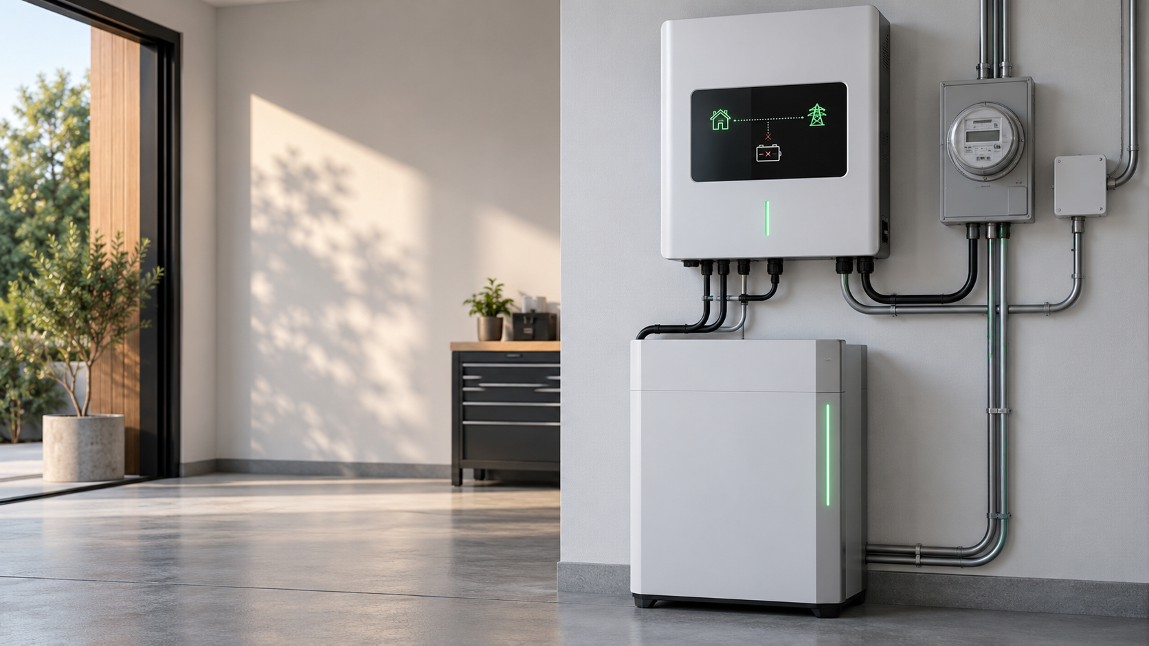
Use the inverter screen and the battery app together. These four states lead to different checks.
| What you see | What it usually points to | First evidence to record |
|---|---|---|
| Battery is missing | Power, breaker, wake-up, CAN/RS485 wiring or basic protocol issue | Battery voltage, breaker state, communication port and inverter alarm |
| Battery is visible, charge current is 0 A | BMS charge permission, charge-current limit, SOC or protection state | Charge Enable, Charge Current Limit, SOC, temperature and cell alarms |
| Battery charges at a small current | Current limit, temperature, SOC ceiling, cell imbalance or inverter setting | Actual current, BMS limit, highest and lowest cell voltage |
| Charging starts, then falls | Power derating, rising temperature, SOC tapering, grid or PV input change | Power trend over time, battery temperature and input power |
A customer record in CVC’s recent field notes describes a 44.8 kWh battery starting near 10 kW and falling to 6–7 kW after 20–30 minutes. That is a derating case. If the display stays at 0 W from the start, begin with permission and protection fields instead.
Start with the inverter screen
Save the complete screen before changing settings. The useful fields are usually spread across the battery, status and settings pages.
- Full inverter model and regional suffix.
- Battery voltage, SOC, charge power and charge current.
- Battery type or lithium profile selected in the inverter.
- Charge source: PV, grid or both.
- Minimum SOC, maximum SOC and charge schedule.
- Battery alarm, BMS status and communication status.
- Firmware version and any setup code or approved battery selection.
For a quote or support case, a photo of the model label is more useful than the short name used in a sales chat. MIN, MOD and SPH are not interchangeable product families, and a low-voltage suffix cannot be treated as a high-voltage configuration.
Read the BMS charge permission
When the inverter sees the battery but charge power remains at 0 W, open the battery BMS screen or service report. Look for the fields below.
| BMS field | How to read it |
|---|---|
| Charge Enable | It must be enabled for the BMS to accept current. A disabled state is a permission issue, not a cable fault. |
| Charge Current Limit | 0 A blocks charging. A low positive value explains a small charging current even when the inverter is ready. |
| Maximum charge current | Compare the BMS continuous limit with the inverter charge-current setting and battery bank configuration. |
| Protection state | Over-voltage, under-voltage, over-temperature, low-temperature or cell fault states can close the charge path. |
| Highest and lowest cell voltage | A large spread can cause the BMS to reduce or stop charging while the inverter still shows the battery online. |
| Contactor and wake status | A sleeping pack, open contactor or protection latch needs a manufacturer or qualified service procedure. |
Do not bypass the BMS or force a charge command from an installer menu. If the pack has a persistent protection latch, no output voltage or a failed contactor, send the evidence to the battery supplier’s service team.
Check SOC, temperature and protection
SOC is not just a display value. The BMS uses SOC, cell voltage and temperature to decide how much charge current to allow.
At high SOC, the BMS may taper current as the cells approach their upper voltage limit. At low temperature, lithium iron phosphate batteries commonly restrict charging below 0 °C. Many residential battery datasheets use a charge operating range around 0–50 °C, while the exact protection threshold belongs to the selected battery model. Read the battery manual rather than copying a value from another pack.
Check the pack temperature, the highest and lowest cell voltage, the SOC limit in the inverter and the time at which charging stopped. If the BMS limit changes from a normal value to 0 A at the same time as a protection alarm, the inverter is following the battery command.
A fully discharged system is another case. CVC customer feedback includes an all-in-one system that could not wake from PV after deep discharge and had a small standby draw. That situation needs a documented wake-up process and service support, not repeated cable swaps. See the home battery reaches 0% troubleshooting guide.
Deye: check the current and battery profile
Deye low-voltage hybrid inverters use a battery-side voltage range around 40–60 V in several residential families. The charge-current figure still belongs to the exact inverter model. In the Deye SUN-3/3.6/5/6K-SG04LP1-EU product information used for this guide, the 5 kW version is listed with 120 A and the 6 kW version with 135 A maximum battery current.
| Deye example | Battery-side reference | What to compare |
|---|---|---|
| SUN-3/3.6/5/6K-SG04LP1-EU family | 40–60 V low-voltage battery input | Battery operating range, BMS current limit and selected lithium profile |
| 5 kW example | 120 A maximum battery current in the referenced product information | Battery continuous current, cable and breaker rating |
| 6 kW example | 135 A maximum battery current in the referenced product information | Battery bank configuration and current sharing |
At 5 kW and 51.2 V, the DC current is about 98 A before conversion losses. At 6 kW it is about 117 A. Those figures explain why the inverter can be online while a BMS with a low or zero charge limit keeps charging off.
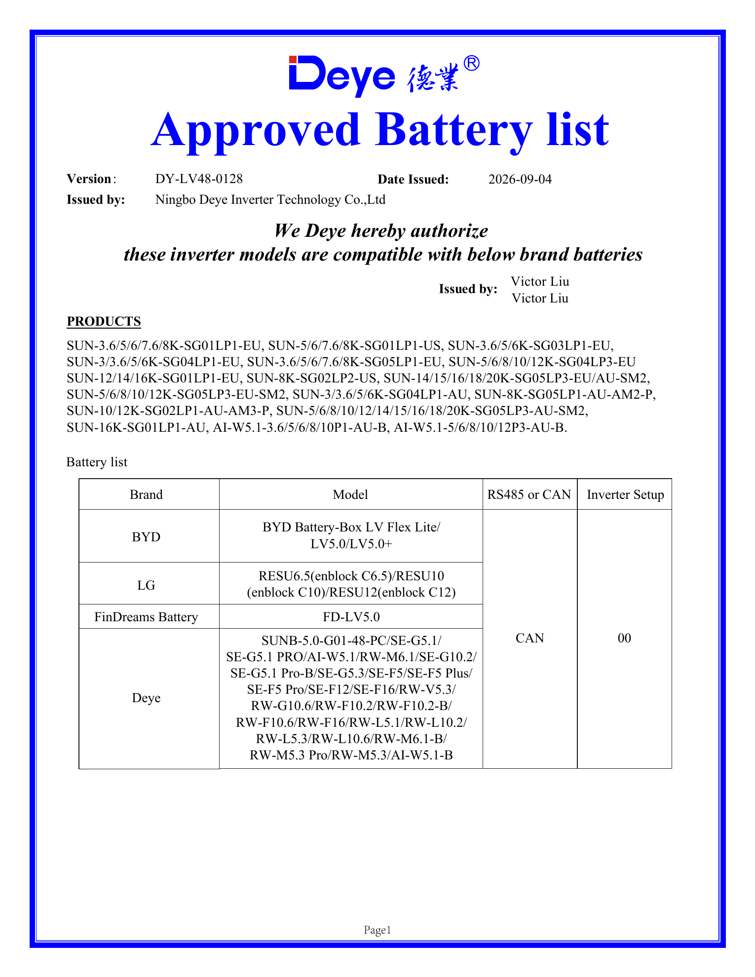
On the Deye screen, check Battery Type, Lithium Mode, battery model selection, charge current, SOC limits, charge schedule and whether PV or grid charging is enabled. Then compare the selected model with the current Deye approved battery list. The connector and the protocol must match the profile that the inverter expects.
Growatt: match the exact inverter and battery family
Growatt support cases need the same discipline. Record the full MIN, MOD or SPH model, the LV or HV designation, the battery series and the BMS communication method. ARK, APX and AXE are different battery families. A working RJ45 connection does not make an ARK, APX or AXE pack interchangeable.
| Growatt item to identify | What to check on the system |
|---|---|
| Inverter family | MIN, MOD or SPH, plus complete model suffix and regional version |
| Battery family | ARK low-voltage, APX high-voltage or AXE low-voltage route, based on the exact product pairing |
| Voltage architecture | Battery voltage range, module count and whether the inverter expects an LV or HV battery |
| Communication profile | CAN or RS485 port, pinout, protocol selection, firmware and battery type |
| Charge permission | Charge Enable, current limit, SOC ceiling, temperature and protection state |
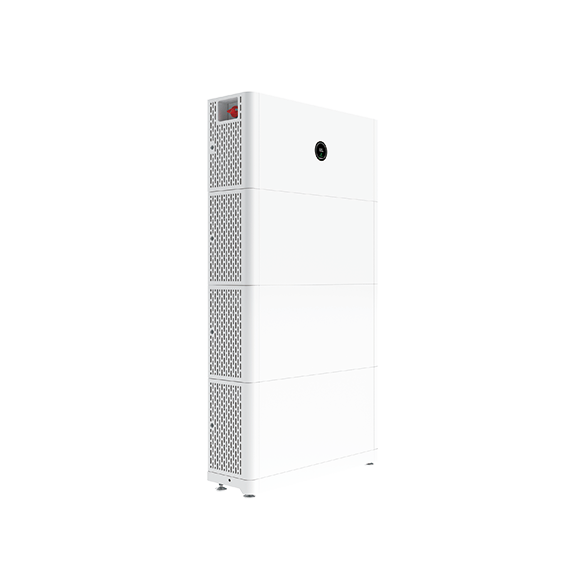
For a Growatt case, save the inverter battery page, the battery BMS page and the firmware screen in the same support package. Check whether the inverter is set to the correct lithium battery profile and whether the selected battery appears in the supported configuration for that model. If the BMS reports Charge Enable = 0 or Charge Current Limit = 0 A, correct the cause in the battery service process before changing the inverter profile.
Our Growatt ARK, APX and AXE comparison explains the battery-family differences. Use it alongside the exact Growatt manual for the model being quoted.
A connected cable is not a verified compatibility match
There are four separate checks between plugging in a cable and getting an approved charging command.
| Level | Question | Evidence |
|---|---|---|
| Physical connection | Is the cable in the correct CAN or RS485 port with the correct pinout? | Port label, wiring photo and continuity check by a qualified installer |
| Electrical range | Does the battery voltage range match the inverter input? | Inverter manual and battery datasheet |
| Protocol profile | Does the BMS speak the profile selected by the inverter? | Battery profile, protocol note and communication log |
| Verified combination | Has this exact model pair been tested or listed? | Approved list, supplier test record or commissioning evidence |
This is why an inverter can display SOC and voltage but still refuse charge current. The basic data frames are visible, but the charge permission, model profile or safety limits are not valid for the selected combination.
Installer checks and service-only work
Distributors and installers can collect the evidence without opening the battery.
| Installer can check | Send to battery or inverter service |
|---|---|
| Full model, voltage, SOC, charge power and alarms | Persistent BMS protection or contactor fault |
| Breaker state, cable port, CAN/RS485 selection and pinout | Firmware flashing or setup-code change |
| Battery type, charge current, SOC limit and charge schedule | Opening the enclosure or replacing the BMS |
| Temperature, cell-voltage spread and BMS current limit | Pack will not wake, has no output voltage or requires a forced-charge procedure |
The customer should not bypass the BMS, short the contactor or force-charge a protected pack. A clear alarm code and a complete screenshot package will get the case resolved faster.
Send a complete support package
When you contact a supplier or service team, send these items together:
- Exact inverter model, battery model and serial number.
- Battery nominal voltage and usable capacity.
- Inverter screen showing SOC, voltage, charge power and current.
- BMS screen showing Charge Enable, Charge Current Limit, temperature and cell-voltage range.
- Alarm code, firmware version and the time the issue occurred.
- CAN or RS485 port photo, pinout information and selected protocol.
- Whether the charge source was PV, grid or generator.
A supplier can diagnose a zero-current case from these records. “The battery is online but not charging” is a starting description. The model, permission and protection data turn it into a solvable case.
CVC can match the complete battery package
CVC helps distributors and installers connect the exact battery, inverter and supplier documents before the quotation is issued. Send the Deye or Growatt model, battery voltage route, target capacity and the screen that shows the zero charge current.
We can coordinate Chinese battery suppliers, compatibility documents, samples and quotations around the actual project. If the battery has already been installed, we can start from the model labels and screenshots. If the project is still at the sourcing stage, we can compare the required CAN/RS485 profile, current rating, firmware record and approved-list evidence before a sample is ordered.
See the energy storage battery range, review the inverter solutions or use the CVC Download Center for compatibility guides and supplier documents.
FAQ
Why does the inverter detect the battery but show 0 A charging?
Start with BMS Charge Enable and Charge Current Limit. Then check SOC ceiling, temperature, cell-voltage protection and the inverter charge mode. The battery can be online while the BMS has closed the charge path.
Can the battery communicate and still be incompatible?
Yes. Voltage and SOC data can appear while the selected protocol profile, model pairing or charge permission is wrong. Check the exact model combination and approved-list record.
Will replacing the CAN or RS485 cable solve the problem?
Only when the evidence points to a wiring, port or pinout fault. If the BMS shows 0 A charge limit or a protection alarm, a new cable will not release charging.
Should the customer replace a battery that has reached 0%?
No. First separate a low-SOC operating state from a deep-discharge wake-up or protection case. Record the BMS status and follow the battery supplier’s documented recovery procedure.
Download and source notes
Download the CVC battery–inverter compatibility guides for a compact checklist of model, voltage, current, protocol and firmware fields.
The Deye current examples in this article use the model information in the Deye SUN-3–6K-SG04LP1-EU manual and the Deye approved-list material available in the CVC Download Center. Growatt family references use the Growatt product and datasheet materials already collected in CVC’s product document library. Always use the exact regional manual and battery configuration for the model being commissioned.

Peter Yin
Need help with a Deye or Growatt battery that does not charge?
Send the exact inverter model, battery model, country, capacity and a screenshot of the zero charge current. CVC can organise a matched battery and supplier follow-up.