
Does a CAN or RS485 battery port prove inverter compatibility?
No. CAN RS485 battery inverter communication is not confirmed by the port type alone. The exact pinout, protocol profile, communication settings, firmware and approved model combination establish the working connection.
CAN and RS485 are common communication interfaces in home energy storage. They connect the battery management system with the inverter so the system can exchange state of charge, voltage, current limits, alarms and operating commands.
For a distributor or installer, the next step is clear: turn the words “CAN supported” or “RS485 supported” into a model-level compatibility record before the quotation is sent. That record should name the battery model, inverter model, BMS protocol, cable definition, communication settings, firmware versions, approved battery list and commissioning result.
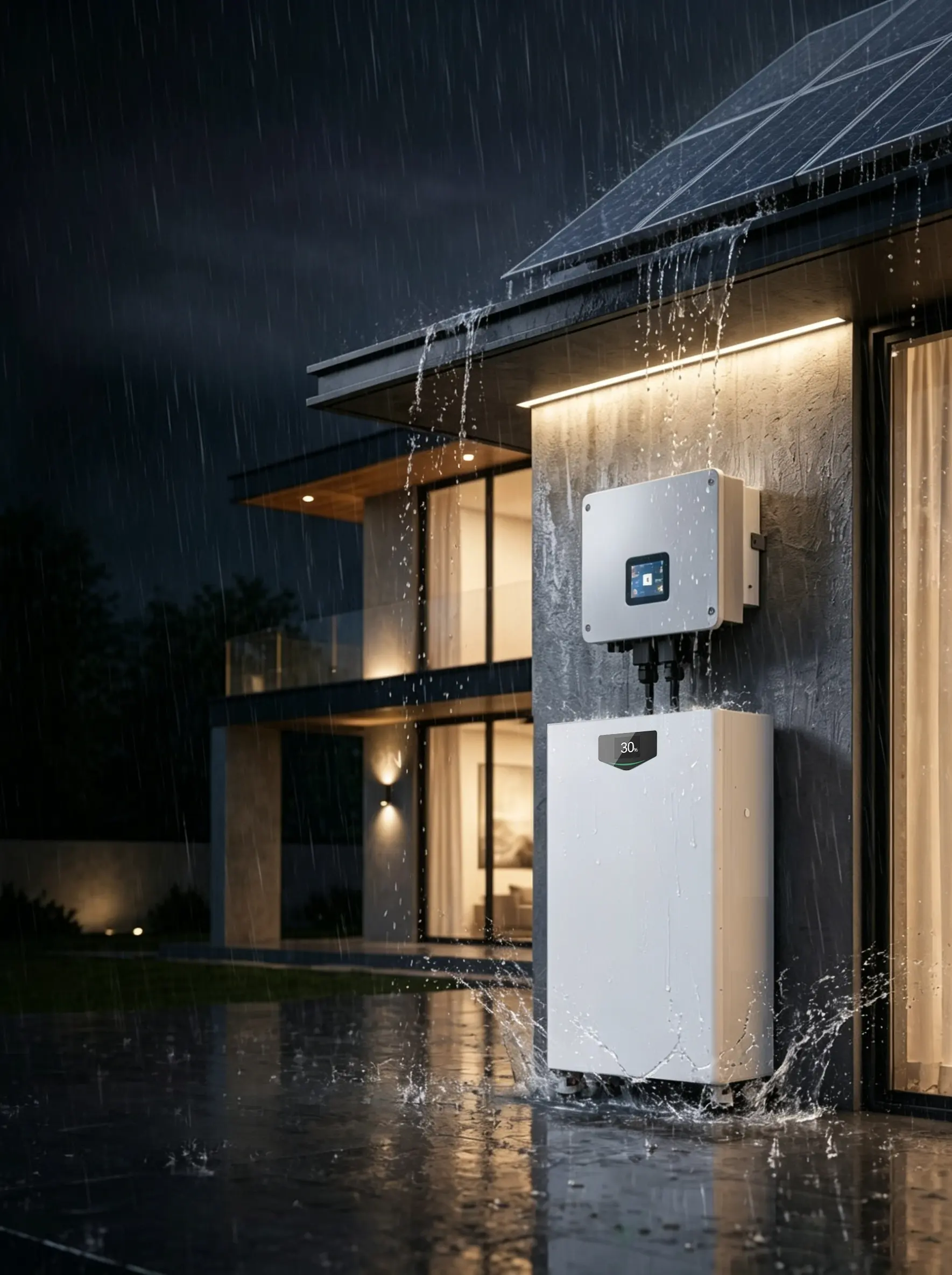
CAN and RS485 are interfaces, not complete compatibility statements
The battery port and inverter port form the physical path. The BMS protocol defines the information sent through that path. The inverter firmware decides how that information is interpreted and how the system responds.
| Item | What it tells the installer | What still needs to be recorded |
|---|---|---|
| CAN | A controller-area network interface is available | CAN-H/CAN-L definition, bitrate, termination, message profile and approved inverter model |
| RS485 | A differential serial communication interface is available | A/B definition, baud rate, parity, stop bits, address, protocol and register map |
| RJ45 connector | The equipment uses a familiar physical connector | The pinout may still differ between manufacturers |
| BMS protocol name | The battery has a defined communication profile | The inverter must support the same profile and data mapping |
| Firmware version | The software version can affect data handling | The battery and inverter versions must be recorded in the approved combination |
The physical interface, protocol and firmware belong in the same compatibility file. Keeping only the interface name leaves the most important information out of the quotation.
The communication data a home battery system must exchange
The BMS communicates the battery condition that the inverter needs to run the system safely and predictably. A typical battery–inverter data set includes:
- battery voltage and current;
- state of charge and state of health, where supported;
- maximum charge current;
- maximum discharge current;
- charge and discharge voltage limits;
- charge, discharge and standby permission;
- temperature or thermal protection status;
- over-voltage, under-voltage and over-current alarms;
- contactor or system-ready status;
- fault codes and recovery state.
The inverter uses these values to control charging, discharging, backup operation and fault response. The battery can show a normal DC voltage while the inverter still refuses to charge or discharge because the BMS profile, address or firmware does not match.
The seven checks before CAN or RS485 is accepted in a quote
1. Record the exact battery and inverter models
Start with the full model names, not a product family name or a marketing series. Add the document revision and firmware version when the supplier provides them.
The same battery family may have different communication settings across capacity versions, BMS revisions or destination-market configurations. The quotation should reference the exact battery model, inverter model and approved configuration.
2. Read the pinout before connecting the cable
CAN commonly uses CAN-H and CAN-L. RS485 commonly uses A and B. The letters are not enough to build a universal cable because manufacturers can assign different pins to the same connector type.
| Wiring field | Record in the project file |
|---|---|
| Connector | RJ45, terminal block or dedicated plug |
| Pin number | Battery-side and inverter-side pin assignment |
| Signal name | CAN-H, CAN-L, RS485-A, RS485-B, GND or shield |
| Cable | Supplied cable, standard cable or project-made cable |
| Shield and ground | Connection method stated in the manual |
| Termination | Required resistor, built-in switch or external termination |
The cable must be checked against both sides of the system. A plug that fits the socket does not prove that the signal pins are aligned.
3. Identify the protocol and data map
CAN and RS485 carry data. They do not define the complete BMS language by themselves.
For RS485, the communication layer may use Modbus RTU or a manufacturer-specific profile. For CAN, the inverter and BMS still need a matching message structure, identifiers and data interpretation.
Ask the supplier for:
- protocol name and version;
- register map or CAN message list;
- voltage, current and SOC data format;
- charge/discharge limit format;
- alarm and fault-code mapping;
- control commands supported by the inverter;
- the approved inverter list for the exact battery model.
The communication interface is confirmed after the inverter can read the battery data it needs and the BMS limits are applied correctly.
4. Record baud rate, bitrate and serial settings
Communication settings are model-specific. A project record can contain values such as CAN at 500 kbps or RS485 at 9600 bps, but the installer must copy the value from the exact product document. These are examples of settings, not universal defaults.
For CAN, record the bitrate, node or message configuration where applicable, termination requirement, and cable length or topology requirements from the product manual.
For RS485, record the baud rate, data bits, parity, stop bits, device address, master/slave role, termination and biasing requirement.
For example, a line written as RS485 / 9600 / 8N1 / address 1 is useful in a commissioning record. The line RS485 supported is not.
5. Check master, slave and parallel-battery settings
When several batteries are connected, one unit may act as the master while other units report as slaves. The system may also require a separate communication cable between battery units and a different cable between the battery group and the inverter.
| Parallel-system item | What to confirm |
|---|---|
| Maximum quantity | Approved number of parallel batteries |
| Master battery | Model, address and switch/DIP setting |
| Slave batteries | Address sequence and communication order |
| Inverter connection | Master port, cable and protocol selection |
| Termination | Last-node termination or built-in termination switch |
| SOC reporting | Group SOC method and display behavior |
| Fault handling | Action when one battery drops offline |
The inverter should receive a stable battery-group status. A group that reports voltage but sends incorrect SOC or current limits is not ready for commissioning.
6. Match firmware and protocol profiles
Firmware can change the supported battery list, alarm behavior, current limits or communication mapping. Record the firmware version of the battery BMS and inverter before a sample is approved.
The same model name should stay linked to the same approved firmware and protocol profile in the quotation, purchase order and installation record. If a factory changes the BMS board or firmware after the sample stage, the communication test must be repeated.
7. Test the live data and control response
The final check is a controlled commissioning record. The installer should confirm that the inverter receives the right data and reacts to the BMS limits.
| Commissioning event | Pass condition | Evidence to keep |
|---|---|---|
| Battery detection | Inverter identifies the correct battery profile | Screen photo or commissioning log |
| Voltage and SOC | Values are stable and reasonable | Inverter and BMS readings |
| Charge limit | Inverter follows the BMS charge-current limit | Recorded charge limit |
| Discharge limit | Inverter follows the BMS discharge-current limit | Recorded discharge limit |
| Alarm response | Battery alarm appears in the inverter interface | Alarm code and time |
| Communication loss | System enters the documented protection state | Test result and recovery action |
| Restart | Battery and inverter return to the approved operating mode | Restart record |
The supplier’s compatibility statement and the installer’s sample test form one evidence chain. A logo list or a port label does not replace the live test.
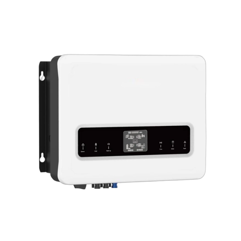
Real parameter example: M16S314BL-YV 16.076 kWh battery
The M16S314BL-YV is a useful example for reading a battery communication specification. Its product record lists the following electrical and communication data:
| Parameter | M16S314BL-YV listed value | How to use the value |
|---|---|---|
| Chemistry | LiFePO4 | Confirm the BMS and inverter charge profile |
| Configuration | 16S1P | Read together with the voltage limits |
| Rated voltage | 51.2 V | Compare with the inverter’s battery operating range |
| Rated capacity | 314 Ah | Used with voltage to calculate nominal energy |
| Total energy | 16.076 kWh | Stored energy, not communication approval |
| Maximum charge current | 200 A | Compare with the inverter and cable limits |
| Maximum discharge current | 200 A | Compare with the inverter output requirement |
| Cycle life | ≥6,000 cycles at 80% DOD, 25°C | Keep the test condition with the figure |
| Communication | RS485, CAN and RS232 | Request the active port, profile, pinout and settings |
| Protection option | IP21 / IP65 optional | Confirm the delivered SKU and installation condition |
The battery’s nominal DC power at the maximum current is approximately:
51.2 V × 200 A = 10.24 kW
That number helps the installer compare the battery with an inverter’s DC current and power limits. It does not establish CAN or RS485 compatibility. The communication file still needs to identify the BMS profile, cable definition, settings, firmware and approved inverter models.
The M16S314BL-YV product page is available in CVC’s 16 kWh LiFePO4 home battery range. Its factory source record lists RS485, CAN and RS232 as available communication interfaces. The exact interface used in a project must be recorded with the selected inverter and delivered configuration.
Integrated system example: YR-AIO6.2-M10
An all-in-one system changes the wiring task because the battery and inverter are delivered as one product platform. The communication function still needs to be understood when the system is monitored, expanded or connected to external equipment.
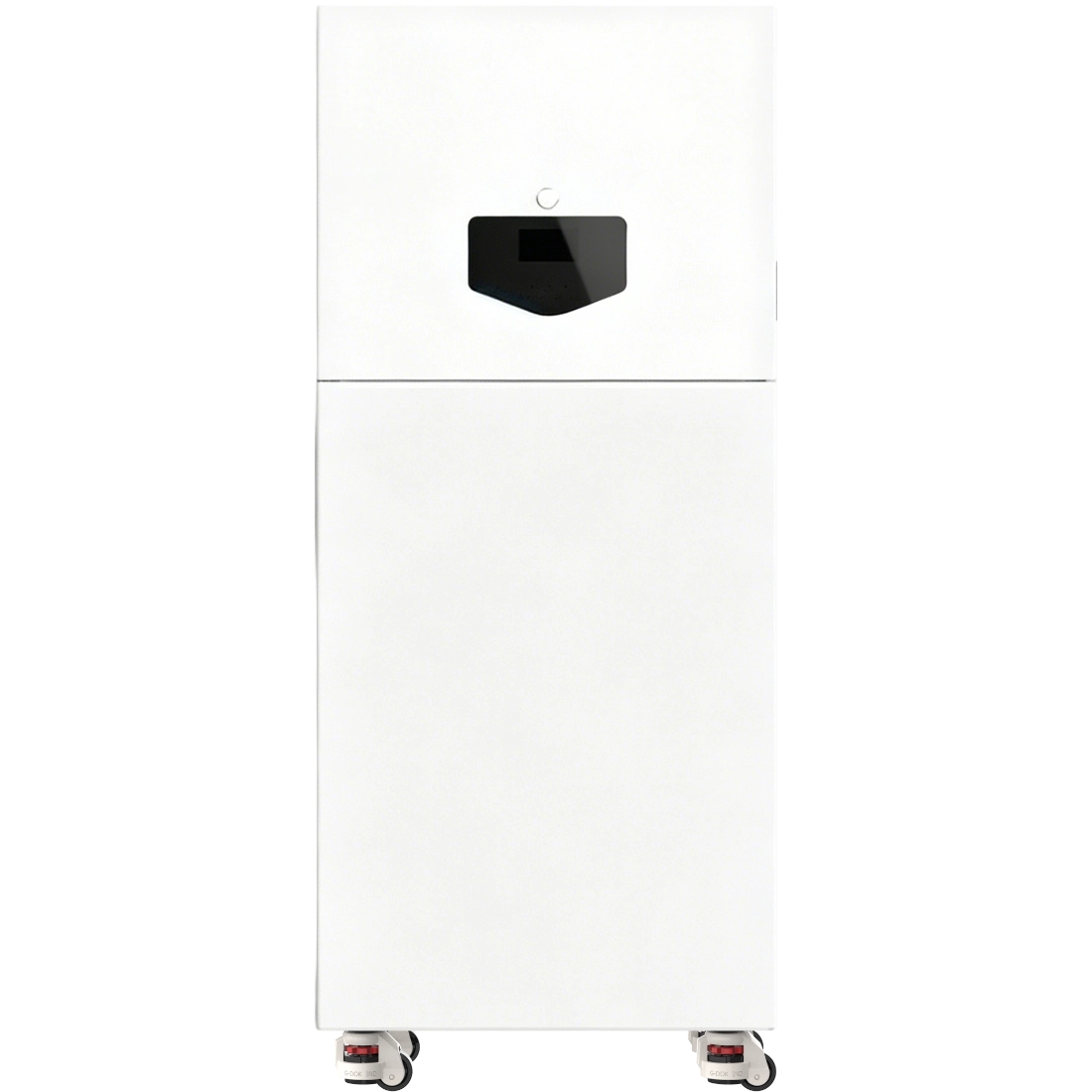
| Parameter | YR-AIO6.2-M10 listed value | What the installer should read |
|---|---|---|
| Rated battery energy | 10.54 kWh | Storage capacity of the selected configuration |
| Battery voltage | 51.2 V | Nominal platform voltage |
| Battery operating voltage | 42–58.4 V | Use the full operating range in system matching |
| Standard charge current | 40 A | Normal charge reference for the battery module |
| Maximum charge/discharge current | 200 A / 200 A | Battery limit; inverter control still matters |
| Inverter model | YR-6248SMH | Record the exact integrated inverter model |
| Inverter rated power | 6.2 kW | AC output class of the integrated inverter |
| Battery input | 56.4 VDC | Compare with the battery operating and charge values |
| AC output | 220 / 230 / 240 VAC ±5% | Match the target grid and project wiring |
| Communication | RS485 / CAN / RS232 | Confirm the active ports and system use |
| Maximum parallel units | 9 | Record the approved expansion and addressing method |
| Enclosure ratings | Battery IP55 / inverter IP20 | Use the rating for the correct enclosure section |
The 51.2 V nominal battery platform and 6.2 kW inverter are useful starting points for a product review. The listed communication interfaces still need a model-specific operating record if the system is connected to external monitoring, a parallel system or a different inverter platform.
The YR-AIO6.2-M10 all-in-one energy storage system is a practical example of why product data should be read as a set. Battery energy, current, voltage, inverter power and communication interfaces belong in one configuration record.
A clean CAN/RS485 verification sheet for the RFQ
Use the following fields in the first quotation request:
| Buyer provides | Supplier confirms |
|---|---|
| Battery brand and exact model | BMS model, revision and firmware |
| Inverter brand and exact model | Approved battery profile or compatibility row |
| Battery voltage and capacity | Operating voltage, charge limits and current limits |
| Required communication | CAN, RS485 or another documented interface |
| Cable route | Connector, pinout, shield and ground method |
| Communication settings | CAN bitrate or RS485 baud/parity/stop/address |
| Parallel quantity | Master/slave method and termination |
| Monitoring requirement | SOC, voltage, current, alarms and fault codes available |
| Target country and grid | Voltage, frequency and local configuration |
| Sample quantity | Commissioning plan and acceptance record |
The supplier response should return the same fields. That keeps the approved sample linked to the production order.
Four common communication mistakes in home storage projects
Mistake 1: Treating a port name as a protocol match
The quotation says “CAN supported,” but the protocol profile, message mapping and approved inverter list are missing. Request the communication document for the exact battery and inverter models.
Mistake 2: Using an RJ45 cable from another product
The connector fits, but the signal assignment may differ. Use the battery-side and inverter-side pinout in the project file before selecting or making the cable.
Mistake 3: Copying settings from a similar battery
A 51.2 V battery does not make its baud rate, address or protocol profile interchangeable with another 51.2 V battery. Copy the settings from the approved model record.
Mistake 4: Checking SOC only after the installation fails
SOC, charge limit, discharge limit and alarm data should be checked during the sample commissioning stage. The record then becomes part of the purchase and installation package.
CAN and RS485 support in CVC product matching
CVC’s battery and inverter compatibility checklist explains the wider matching chain: voltage, current, BMS communication, firmware, operating mode and supplier documents. For projects comparing Deye and Growatt inverter families, use the model-level battery compatibility guide as the starting point and add the exact battery protocol record to the RFQ.
CVC can help buyers organize:
- battery and inverter model matching;
- CAN/RS485 protocol and pinout documents;
- firmware and approved compatibility records;
- sample commissioning files;
- battery, inverter and all-in-one product options;
- factory communication for distributor and installer projects.
The input should include the battery model, inverter model, target country, expected quantity, backup requirement and communication interface already shown on the products. Send the project details through the CVC contact page or review the available technical material on the CVC Downloads page.
Buyer FAQ
CAN and RS485 in the same battery system
A battery may list both CAN and RS485. The installer should use the interface specified by the approved inverter profile and keep the port, cable, settings and protocol record together. The second interface may serve another device, a parallel-battery link or a different integration route.
A battery shows voltage but the inverter shows a communication fault
Check the exact cable pinout, protocol selection, baud rate or CAN bitrate, device address, termination, master/slave setting and firmware. Then review the battery profile selected in the inverter menu and repeat the controlled commissioning test.
Communication during an inverter replacement
Keep the battery model, BMS firmware and existing communication record. Match the replacement inverter against the same voltage, current, protocol and firmware requirements. Re-run the sample verification before the replacement is approved for a customer installation.
Parallel batteries and SOC display
The supplier should state the master battery, address sequence, maximum parallel quantity, termination method and group-SOC logic. Record the displayed SOC and current limits during commissioning.
The communication record belongs in the quotation
CAN and RS485 checks become straightforward when the quotation uses the exact models and records the full communication chain. Start with the interface. Then add the pinout, protocol, settings, firmware, master/slave logic and live test result.
Send CVC the battery model, inverter model, target market, communication requirement and purchase quantity. CVC can help identify the matching factory supply path and assemble the technical information needed for a controlled quotation.

Peter Yin
Request a CAN/RS485 Compatibility Review
Send your battery model, inverter model, target country, communication requirement, expected quantity and available protocol documents. CVC can help identify the matching supply path and technical information for the quotation.