
The short answer
Can a 10 kW inverter be paired with any 20 kWh battery in a three-phase home system? No. The phase structure, battery current and backup mode still need to match.
Does a three-phase home need the same battery power on every phase? No. The load on each phase and the inverter’s phase limits control the result.
If the battery voltage and nominal capacity match the inverter, is the quotation ready? No. BMS communication, firmware, current and operating-mode data complete the check.
A three-phase battery inverter compatibility check begins with the phase structure, backup loads, continuous and surge power, battery voltage range, BMS communication and operating mode.
The fastest way to create a mismatch is to quote from two numbers alone: battery kWh and inverter kW. A 19.2 kWh battery can be connected to a 10 kVA three-phase inverter on paper, yet the battery-side current, backup circuit and communication settings can still determine how much power the system can actually deliver.
This checklist is for distributors, installers and system integrators preparing a residential or small commercial three-phase storage quotation.

Start with the phase structure, not the battery size
Record the system topology before comparing products:
- three-phase grid connection or three single-phase inverters working as a three-phase system;
- on-grid, backup, off-grid or generator-assisted operation;
- whether backup power must remain available on all three phases;
- the load on each phase;
- the largest motor, compressor, pump or heating load;
- the circuits that will be connected to the backup output.
A home may have a 9 kW total load, but that figure does not explain how the load is distributed. If one phase carries a 5 kW pump and air-conditioner combination while the other two phases carry light household loads, the phase-by-phase output limit matters more than the average total.
The quotation should therefore contain a phase load sheet alongside the total-load figure.
The six checks behind a reliable three-phase match
1. Phase output and backup circuit
Confirm the inverter’s output configuration and the way it handles single-phase loads. The installer should record:
| Quotation field | What to record | Evidence to request |
|---|---|---|
| Grid connection | Three-phase voltage and frequency | Inverter datasheet |
| Backup output | Three-phase or selected backup phases | Wiring diagram and manual |
| Single-phase loads | Load value on each phase | Customer load list |
| Phase balance | Maximum permitted imbalance | Inverter technical data |
| Backup boundary | Circuits included during an outage | Backup-panel diagram |
Do not use the total household load as a substitute for the backup-panel load. The system is sized around the circuits that must remain powered.
2. Continuous power, peak power and battery current
Separate these three figures:
- inverter rated AC power;
- short-duration or maximum apparent power;
- battery-side continuous charge and discharge current.
The inverter may show a 10 kVA AC rating, while the battery and DC input define how much power can be supplied during a battery-only backup event. Motors and compressors also need a startup check, because their inrush current can be much higher than their running power.
For the RFQ, ask the supplier to state the continuous output and peak output for the selected operating mode. Record the duration of the peak value as well.
3. Battery voltage window and DC operating point
The battery’s nominal voltage must sit inside the inverter’s working range. Then check the upper and lower operating limits, maximum current and the voltage at which the inverter reaches its rated output.
The basic calculation is:
DC power ≈ battery voltage × battery current × conversion efficiency
The calculation is simple. The data sheet is where the useful answer is found.
4. Capacity, usable energy and backup time
Battery energy and inverter power answer different questions:
- kWh indicates how much energy the battery stores;
- kW or kVA indicates how much power the system can deliver at a given moment;
- usable energy determines the practical backup time;
- the critical-load list determines the actual demand.
For planning, use the manufacturer’s stated usable energy. Do not treat a cycle-life test condition such as “80% DOD” as an automatic daily usable-capacity guarantee. Ask the supplier to identify nominal energy, usable energy, recommended operating SOC range and the conditions used for each figure.
5. BMS communication and firmware
The battery and inverter must share a confirmed communication path. Record:
- CAN or RS485;
- protocol name;
- cable and pinout;
- baud rate or CAN settings;
- battery address and master-battery setting;
- approved inverter models;
- BMS and inverter firmware versions.
The phrase “CAN/RS485 supported” is only the first line of a compatibility check. Use the battery compatibility guide for Deye and Growatt inverters when the project involves those inverter families, then ask the supplier for the exact model and firmware match.
6. Grid, backup and PV operating modes
The same hardware can behave differently in on-grid, backup and off-grid operation. Add these fields to the quotation:
| Operating item | Information to confirm |
|---|---|
| Grid voltage and frequency | Local grid specification and inverter setting |
| Backup transfer | Transfer method and stated response time |
| PV input | Maximum DC input, MPPT range and tracker count |
| Generator input | Supported input and control method |
| Export control | Zero-export or feed-in configuration |
| Restart behavior | Startup sequence after grid recovery |
This information belongs in the system quotation because it changes the wiring, control settings and customer expectation.
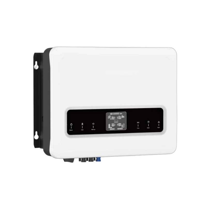
Parameter reading example: YR-SYS620-3P10-19.2
The following configuration shows how to read a real product data set during a quotation review. The system combines a high-voltage LFP battery with a three-phase hybrid inverter.
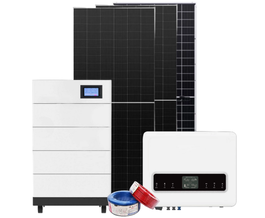
Published configuration
| Component | Parameter | Listed value | What the buyer should read from it |
|---|---|---|---|
| Battery | Model | HVM60S100BL | Use the exact battery model in the RFQ |
| Battery | Energy | 19.2 kWh | Stored energy, not instantaneous output power |
| Battery | Nominal voltage | 192 V | High-voltage battery platform |
| Battery | Charge/discharge current | 100 A / 100 A | Battery-side current capability stated by the battery data |
| Battery | Chemistry | LFP | Confirm the exact cell and BMS configuration in the document pack |
| Battery | Cycle life | ≥6,000 cycles at 80% DOD, 25°C | Test condition and temperature must stay with the figure |
| Battery | Communication | RS485 / CAN | Protocol, pinout and inverter list still need to be matched |
| Battery | Protection | IP54 | Use the battery installation requirements for the final location |
| Inverter | Model | EPH10KTL | Record the exact model; “10 kW” is not enough |
| Inverter | Rated AC power | 10,000 VA | Three-phase AC output rating |
| Inverter | Maximum apparent power | 11,000 VA | Short-term or operating-limit figure; confirm its duration |
| Inverter | AC voltage/frequency | 400 V / 50 Hz | Match the target grid and project wiring |
| Inverter | Battery voltage range | 130–700 V | The 192 V battery nominal voltage sits inside the listed range |
| Inverter | Maximum battery current | 25 A / 25 A | A key number for the battery-side power check |
| Inverter | Backup output | 10,000 VA | Check the backup-panel and phase limits behind this rating |
| Inverter | Maximum DC input | 15,000 W | Compare with the planned PV array |
| Inverter | MPPT range / trackers | 200–850 V / 2 | Check PV string voltage and tracker allocation |
| Inverter | Maximum efficiency | 98.20% | Use as a conversion reference, not as the customer’s guaranteed runtime |
Product data source: YR-SYS620-3P10-19.2 three-phase solar storage system. The matching product page is also available on CVC: YR-SYS620-3P10-19.2 high-voltage solar storage system.
What this example tells the buyer
The first check passes at the nominal-voltage level: the 192 V battery is inside the inverter’s stated 130–700 V battery range. That is useful, but it is only one line of the match.
The next check is more important. At 192 V and 25 A, the listed inverter-side current corresponds to approximately 4.8 kW of DC power before conversion losses:
192 V × 25 A = 4,800 W
If the battery is expected to supply the full 10 kW backup output, the rough DC-side requirement at 192 V is about 52 A before conversion losses:
10,000 W ÷ 192 V ≈ 52 A
This is the exact point where a buyer should request the supplier’s battery-side power curve or written operating clarification. The AC nameplate and the battery-side current line must describe the same operating condition before the quote is presented as a full-power battery backup package.
The example also shows why the 19.2 kWh figure cannot be used alone. It describes stored energy. It does not prove that the battery can deliver the inverter’s full AC rating at every battery voltage, in every phase configuration or in every backup mode.
The right quotation records the relationship between the numbers:
- 192 V battery nominal voltage;
- 130–700 V inverter battery range;
- 25 A listed inverter-side battery current;
- 10 kVA AC and backup output rating;
- the supplier’s confirmed full-power operating condition.
That is how a buyer compares a second product. Replace the model, voltage and current values in the same table, then check whether the supplier provides the same evidence.
A practical RFQ checklist for three-phase systems
Send the following information with the inquiry:
| Buyer provides | Supplier confirms |
|---|---|
| Target country and grid specification | Applicable voltage and frequency version |
| Three-phase or three single-phase topology | Output structure and phase-control method |
| Load on each phase | Continuous and peak output by phase |
| Backup-panel circuit list | Backup output limit and transfer behavior |
| Largest motor or compressor | Startup handling and surge duration |
| Target battery energy | Nominal and usable energy |
| Battery voltage preference | Operating voltage range and current |
| Inverter brand and model | BMS protocol, pinout and firmware match |
| PV array design | MPPT range, tracker count and maximum DC input |
| Quantity and delivery market | Datasheet, manual, warranty and export documents |
If these fields are complete, a supplier can compare an actual system configuration instead of sending a generic battery price.
Product direction for three-phase projects
CVC’s three-phase residential hybrid inverter range and hybrid inverter solutions can be used as the starting point for product matching. The home energy storage battery range provides the battery side of the comparison. For a broader pre-quotation review, use the battery–inverter compatibility checklist before quoting. Review the relevant product datasheets and compatibility documents before requesting a quote.
For a project review, CVC can help organize:
- the battery and inverter model combination;
- phase and backup-load information;
- voltage, current and BMS communication data;
- datasheets, manuals and compatibility files;
- sample and bulk-quantity quotation requests;
- export coordination for the target market.
The useful input is specific: send the inverter model, battery voltage, critical-load list, PV plan, target country and quantity through the CVC contact page.
Buyer FAQ
Three-phase systems with single-phase household loads
Single-phase household loads can be part of a three-phase storage project. The installer still needs the load value on each phase and the inverter’s permitted phase imbalance. The total load figure is not enough.
Battery energy versus inverter output power
19.2 kWh tells you how much energy is stored. A 10 kVA inverter rating tells you the AC output class. Battery voltage, current and the operating mode connect the two figures.
High-voltage battery versus low-voltage battery
Choose the battery platform that matches the inverter’s voltage window, current requirement, BMS protocol and installation design. A nominal voltage label alone does not complete the selection.
CAN and RS485 confirmation
Ask for the protocol name, pinout, communication settings, firmware version and approved inverter list. The interface label is only the starting point.
Get the matching data before the quote
A three-phase quotation becomes reliable when the phase load, power, voltage, current, communication and operating mode are recorded together. Start with the actual model numbers. Then compare the data line by line.
Send CVC your battery model, inverter model, target market, critical-load list and purchase quantity. CVC can help identify a matching supply path and prepare the technical information needed for the next quotation step.

Peter Yin
Request a Three-Phase System Matching Review
Send your country, grid specification, phase load sheet, critical-load list, candidate battery and inverter models, PV plan and expected quantity. CVC can help identify the matching supply path and technical documents for the quotation.