
Why does a running generator still make a battery system switch to UPS?
Generator battery storage systems can stay connected to a running generator, yet the inverter can fail the AC-input test for a short moment. The inverter sees a voltage dip, frequency movement or a distorted waveform, leaves the generator input and supplies the backed-up loads from the battery. If the generator recovers, the inverter tries the input again. That repeated accept–reject cycle is the UPS switching customers notice.
The quickest way to reduce it is to create headroom: lower the generator-side battery charging power, keep motor starts away from the charging step, select the correct generator input mode and measure voltage at the inverter terminals. Adding more battery capacity does not correct an unstable AC source.
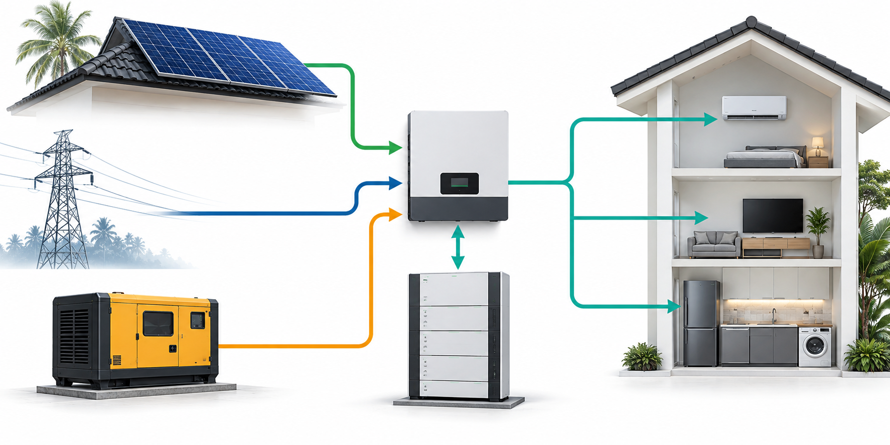
Separate the two voltage problems before changing settings
“Voltage dip” can describe two different events. Check which side of the inverter reported the event first.
| What the customer sees | Where to measure first | What usually needs attention |
|---|---|---|
| Generator is running, but the inverter drops generator input and the loads transfer to UPS/battery | AC voltage and frequency at the inverter’s generator input terminals | Generator response, charge power, input current limit, wiring drop, ATS contacts and inverter acceptance window |
| Battery output trips when a load starts, even while the generator input is stable | Battery terminals and inverter DC terminals during the load step | BMS current limit, battery voltage sag, cable drop, inverter peak power and motor starting current |
| Both events appear together | Record AC and DC values with the same timestamp | A load step may be pulling down the generator and pushing the battery side toward its protection limit |
The first row is the focus of this article. For a pump-start event on the battery side, see Why Does a Battery Trip When a Water Pump Starts?. Keeping the two diagnoses separate prevents a generator-input problem from being “fixed” by changing battery settings.
Reduce switching first: keep headroom on the generator
Battery charging is an electrical load on the generator. A generator sized only for the household loads can still overload when it charges the battery at the same time. Motor starting makes the margin smaller because pumps, compressors and refrigerators demand a short surge and a lower power factor.
Use the current calculation before changing the charge limit:
| Example at 230 V | Calculation | What it tells the installer |
|---|---|---|
| 5 kW resistive-equivalent load, power factor 1.0 | 5,000 ÷ 230 ≈ 21.7 A | The generator and wiring must carry at least this load before battery charging is added. |
| 5 kW load, power factor 0.8 | 5 kW ÷ 0.8 = 6.25 kVA; 6,250 ÷ 230 ≈ 27.2 A | The generator sees more apparent power and current than the kW number suggests. |
| 10 kW load, power factor 0.8 | 10 kW ÷ 0.8 = 12.5 kVA; 12,500 ÷ 230 ≈ 54.3 A | A large motor or mixed load can consume the generator margin before the battery charger reaches its nameplate limit. |
- Record the generator’s continuous kW/kVA rating and the household load while the generator is stable.
- Reduce the inverter’s AC charging power or current so the generator has room for the largest expected load step.
- Run the same charge cycle again and increase the limit only after the voltage and frequency remain stable at the inverter input.
For a multi-day outage, the aim is not the highest possible charge rate at every moment. It is a recharge rate the generator can hold without repeated transfers. The broader recharge logic is covered in Multi-Day Home Battery Backup: Why Recharge Planning Matters More Than Battery Size.
Use the generator input mode and limits correctly
Hybrid inverters normally provide a generator or weak-grid input mode. Set the input source type first, then review the input current limit, battery charge limit, frequency range, start delay and reconnection delay shown for that exact inverter model. The goal is a stable acceptance decision, not simply a wider protection window.
Victron’s MultiPlus-II configuration documentation gives a useful model-specific example. It lists a nominal 230 V input range of about 180–265 V, with example low-voltage disconnect at 180 V and reconnect at 187 V, and high-voltage disconnect at 270 V and reconnect at 265 V. These values belong to that model and configuration; they show why a generator that measures “230 V” with no load can still be rejected during a load step. A small generator with slow voltage recovery may cross the window for a fraction of a second and trigger the transfer.
Read the exact inverter manual, select the correct 50/60 Hz version and adjust the generator charging limit before changing UPS sensitivity. Do not bypass anti-islanding or protection functions. Victron also documents generator-related input behaviour in its MultiPlus-II configuration guide and MultiPlus FAQ.
Stagger motor starts and battery charging
Do not let the generator start a pump, air-conditioner compressor, freezer or workshop tool at the same time that the inverter begins a high-power battery charge. A 5 kW continuous load can be manageable while a motor start briefly pushes the generator beyond its voltage-response capability.
- Let the generator reach stable voltage and frequency before enabling battery charging.
- Delay the largest motor load after generator start and after a charging step.
- Use a soft starter or variable-frequency drive where the motor and installer design support it.
- Put non-critical water heating, EV charging and workshop loads outside the backed-up output during charging.
- Set load priority so refrigerator, router, lighting and communications remain online while flexible loads wait.
This is a control sequence, not a battery-size problem. The pump itself still needs the starting-current check described in the water-pump protection guide.
Check the complete AC path, not only the generator display
Measure the generator terminals and the inverter AC-input terminals during the same event. A generator can show a normal value at its own panel while a long cable, undersized conductor, loose terminal, breaker, ATS contact or neutral connection creates a short dip at the inverter.
| Checkpoint | Record | Why it matters |
|---|---|---|
| Generator output terminals | Line voltage, frequency, load kW/kVA and power factor | Shows the source response before the distribution path. |
| ATS and breaker connections | Voltage on both sides during charge and motor start | Reveals contact resistance or a switching-device drop. |
| Inverter AC-input terminals | Voltage, frequency and event timestamp | This is the value used by the inverter’s acceptance logic. |
| Battery DC terminals | Voltage, charge current, SOC and BMS state | Separates an AC-input rejection from a battery-side protection event. |
Run three repeatable tests
A single voltage reading rarely identifies a switching problem. Run the same three tests and record the exact moment the inverter changes source.
| Test | Operating condition | Record |
|---|---|---|
| 1. Generator no-load test | Generator warmed up, battery charging disabled | Voltage, frequency, waveform or THD if the instrument provides it, and recovery after a small load. |
| 2. Charging test | Generator stable, battery charging at the proposed setting | AC input value, generator load, charge power, battery SOC and inverter event code. |
| 3. Load-step test | Charging active, then start the pump, compressor or largest planned load | Voltage at generator and inverter, minimum value, recovery time and whether the inverter transfers to UPS. |
Keep a timestamped photo of the inverter screen, generator panel and BMS/app screen for each test. The installer or manufacturer can then compare the measured values with the model’s acceptance window and wiring design. This record is also useful when evaluating a replacement generator or a different inverter.
A practical checklist to reduce repeated UPS switching
| Priority | Action | Result to look for |
|---|---|---|
| 1 | Lower AC battery charging power/current | Generator voltage stays inside the inverter input window. |
| 2 | Select the generator input mode and set the model-specific current limit | Charging and load support remain within generator capacity. |
| 3 | Delay pumps, compressors and other motor starts | No large voltage step occurs during the charging transition. |
| 4 | Separate flexible loads from the critical-load output | Essential loads remain powered while the generator recovers. |
| 5 | Measure generator and inverter terminals together | Cable, breaker or ATS voltage drop is visible. |
| 6 | Review event logs, frequency and reconnection timing | The repeating trigger is identified instead of guessed. |
| 7 | Send the complete record to qualified service | Settings and wiring changes follow the inverter and generator manuals. |
Questions installers hear most often
Why does the inverter switch to UPS while the generator is still running?
Because the inverter evaluates the voltage, frequency and waveform at its own AC input. A short dip during charging or motor starting can make that input fail the acceptance window even while the generator engine continues to run.
Will a bigger battery stop the switching?
No. More battery capacity increases runtime. It does not correct generator voltage recovery, cable drop, a high charge-current setting or a motor-start event.
Can I turn off UPS mode when using a generator?
Use the inverter’s documented generator mode and charging limits. Keep the protection and anti-islanding functions enabled, and have a qualified installer handle any wiring or threshold change.

Peter Yin
Send a Project Inquiry
Tell us your country, generator model, inverter model, battery voltage, critical loads and expected quantity.