
Why does a battery trip the moment a water pump starts? The usual reason is not low kWh capacity. The pump creates a short starting surge, the inverter pulls extra DC current, and one protection layer reaches its limit before the pump settles into normal running power. The first job is to identify which layer tripped: the battery BMS, the inverter, the AC breaker or the wiring.
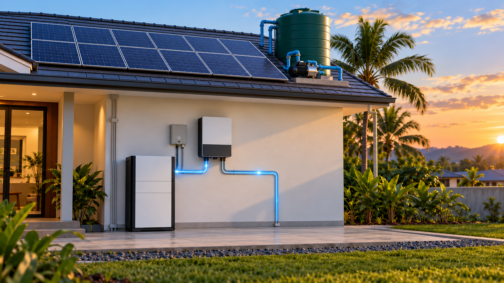
1. First identify which protection layer tripped
Do not start by replacing the battery. Read the alarm screen, inverter event log and breaker position first. The same pump symptom can come from different parts of the system.
| What you see | Likely protection layer | What to inspect |
|---|---|---|
| Battery alarm appears and the inverter loses battery power | BMS overcurrent, short-circuit or low-voltage protection | Battery current limit, protection threshold and voltage at the battery terminals |
| Inverter shows overload or AC overcurrent | Inverter output or surge limit | Running power, starting power, surge duration and other loads starting at the same time |
| AC breaker trips | AC-side current or short-circuit protection | Pump circuit, breaker rating, cable condition and any fault code |
| Battery voltage drops sharply, then returns after the trip | Voltage sag or BMS low-voltage response | Battery-terminal voltage, inverter-terminal voltage, cable length and cable connections |
| The trip appears mainly at low SOC or in cold weather | Reduced available current or usable voltage window | SOC, cell temperature, charge/discharge limits and the event time |
A clear alarm code helps the installer narrow the fault quickly. A customer can record the code, SOC, PV output and time of the event; the battery enclosure should stay closed and the protection should not be bypassed.
2. A pump running rating does not tell you its starting demand
A 1/2 HP pump rating describes mechanical output, not the complete electrical demand seen by the inverter. A 1/2 HP shaft output is about 373 W, but the electrical input changes with motor efficiency, power factor, pump head, pipe pressure, water level and the pump’s start method.
Read the pump nameplate for voltage, phase, frequency, rated current and locked-rotor current (LRA) when available. For a single-phase pump marked 230 V and 6 A, the simple apparent-power reference is about 1.38 kVA before power factor is considered. If the starting current reaches three times the rated current, the instantaneous apparent demand is about 4.14 kVA. That is why a pump that runs comfortably at normal power can still start an overload or battery-protection event.
A generic 2× or 3× starting factor is a screening estimate, not a quotation value. The motor nameplate, pump controller, soft starter or a clamp-meter test gives the installer a usable design input.
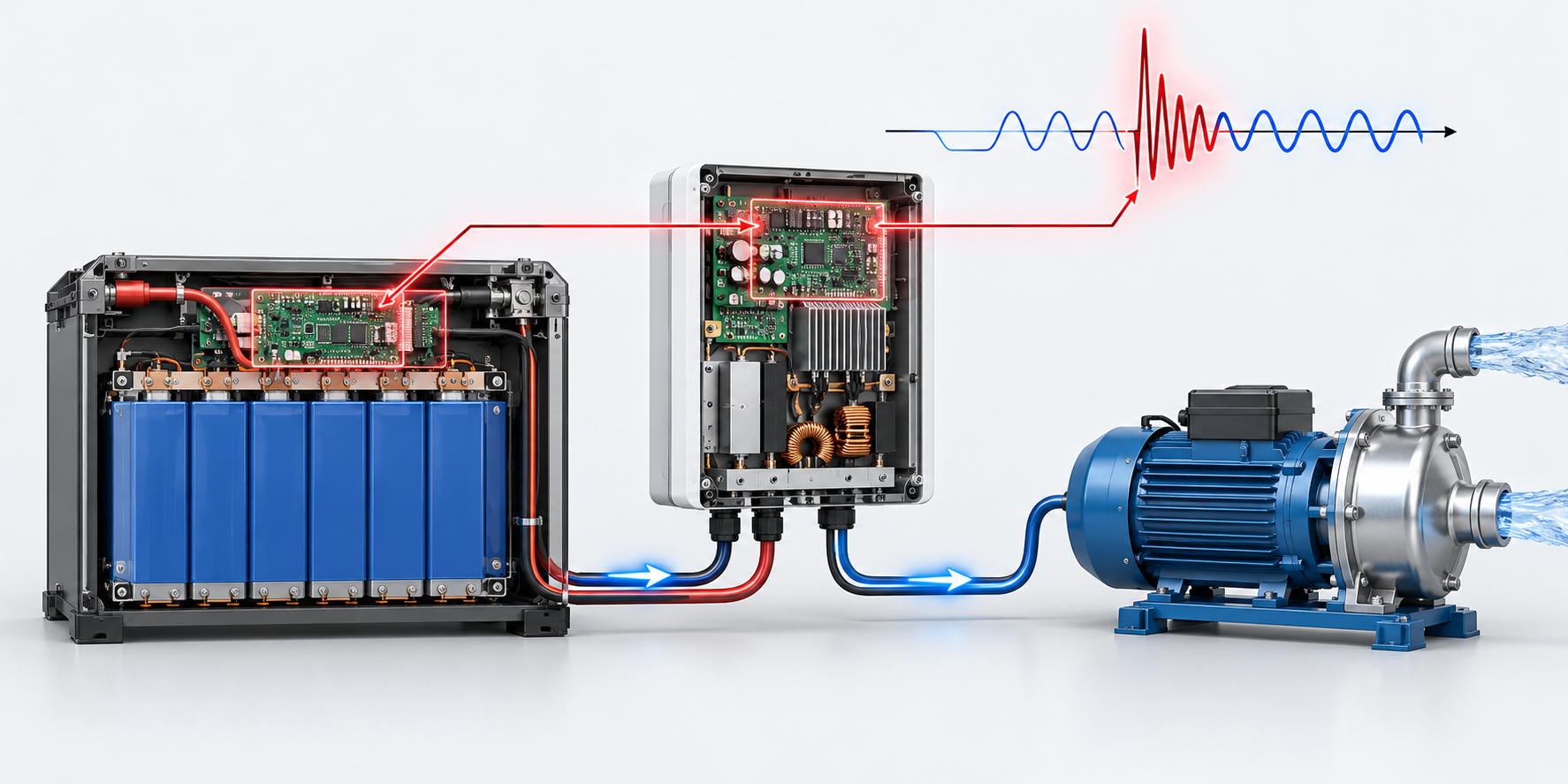
3. Read the battery-side current from a real CVC product
Use the battery voltage and inverter output to estimate the DC current that the battery must supply. The basic relationship is:
IDC ≈ PAC ÷ (Vbattery × η)
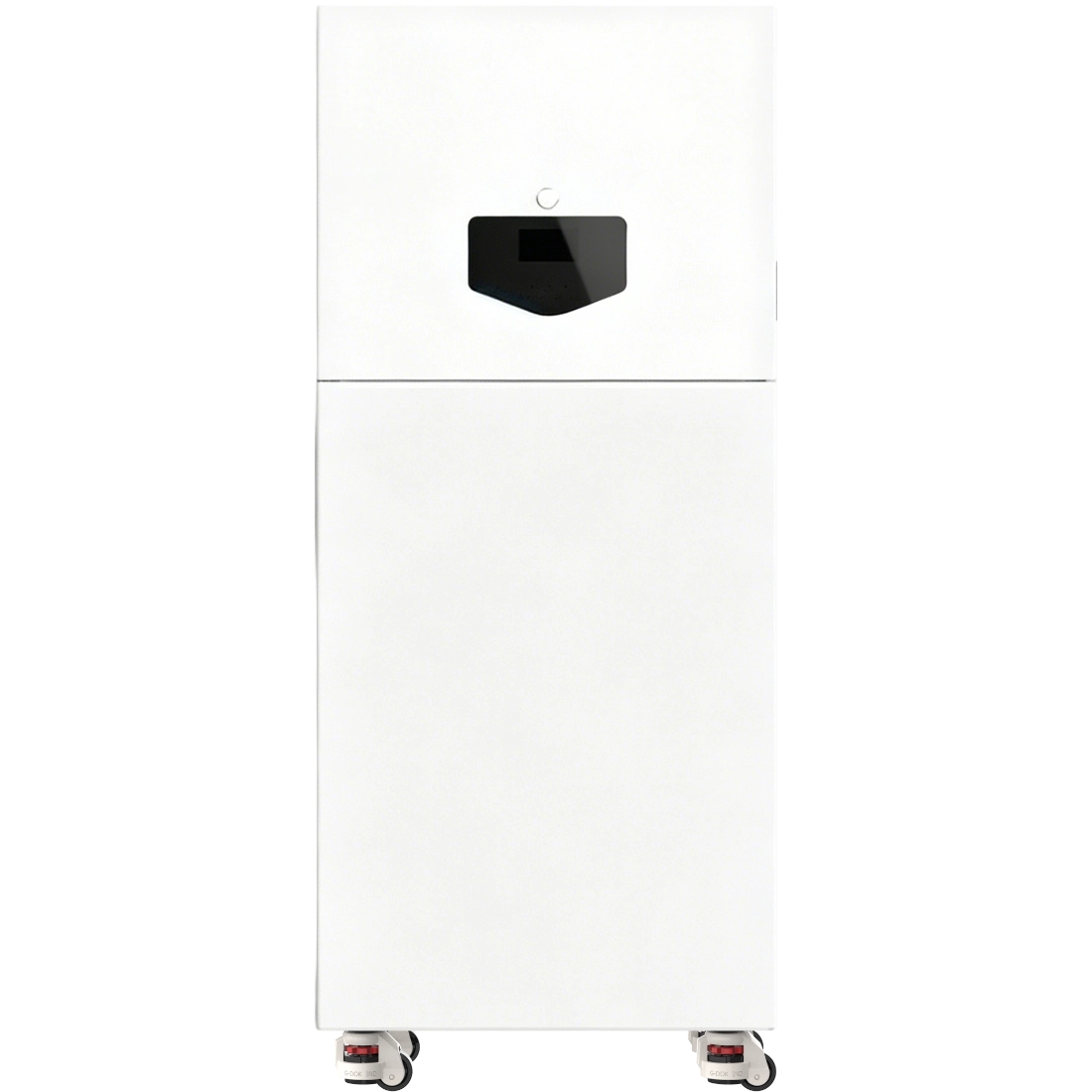
Take the CVC YR-AIO6.2-M10 all-in-one system as a product example. Its listed architecture uses a 51.2 V battery system, a 6.2 kW inverter and 10.54 kWh nominal energy. At the full 6.2 kW inverter output, the ideal DC current is about 121 A at 51.2 V. Using an illustrative 94% conversion efficiency, the calculation becomes about 129 A.
| Parameter | YR-AIO6.2-M10 example | How to use it for a pump check |
|---|---|---|
| Battery voltage | 51.2 V | Use it to convert the AC load into approximate battery-side current. |
| Inverter rated output | 6.2 kW | Compare it with the pump’s running demand and the other loads on the backup output. |
| Nominal battery energy | 10.54 kWh | It indicates energy storage, not the instantaneous current available for motor startup. |
| BMS continuous and peak current | Read the exact model datasheet | Compare the BMS limit with the calculated battery current and the pump’s start event. |
| Pump starting current | Read the nameplate or test value | Use the real current and duration, not only the 1/2 HP label. |
The same current check also applies to other 48 V or 51.2 V systems. Our 48 V and 51.2 V battery–inverter compatibility guide explains the voltage, current and communication fields that must be checked together.
4. Why the pump may work in daylight but trip at night
A customer may report that the pump starts normally during the day but trips the battery at night. That pattern is useful evidence. In daylight, PV power can support the DC bus and reduce the portion of the pump surge drawn from the battery. At night, the battery must provide the full inverter demand.
The available battery current can also change with SOC, cell temperature and the BMS operating limit. Cable voltage drop becomes more visible when the battery is supplying a short, high-current pulse. Daytime success therefore does not prove that the same pump-start event is safe at the lowest SOC or at the coldest operating temperature.
Record two events separately: a daytime start with PV output and SOC, and a night-time start with SOC, battery voltage, inverter power and the alarm code. That comparison is more useful than comparing the pump’s running watts with the battery’s kWh label.
5. What the installer should check—and what the customer should not repair
The customer’s job is to capture the evidence. The installer or qualified after-sales team should interpret the protection thresholds and make any configuration or wiring change.
| Customer can record | Installer or after-sales should verify |
|---|---|
| Pump nameplate photo, model, voltage and phase | Running current, starting current and starting duration |
| Time of trip, SOC, PV output and whether it was day or night | Inverter continuous output, peak output and peak duration |
| Battery and inverter alarm code | BMS continuous/peak current, threshold and delay |
| Other loads running at the same time | Battery-terminal voltage, inverter-terminal voltage and cable drop |
| Whether the system recovered automatically | Cable cross-section, terminal torque, breaker selection and communication status |
Do not open the battery, bypass the BMS, increase protection thresholds, change the breaker or repeatedly force-restart the system. Those actions can hide the original fault and create a safety risk. Send the event record to the equipment supplier or a qualified service technician.
6. Prevent pump-start trips before the quotation
Put four groups of data on the same quotation sheet:
- Pump: model, voltage, phase, rated current, LRA or measured start current, controller and pump head.
- Inverter: rated output, peak output, peak duration, overload behavior and backup-output limits.
- Battery and BMS: voltage range, continuous current, peak current, low-voltage response, temperature limits and communication protocol.
- Installation: cable length and cross-section, terminal condition, breaker, other simultaneous motor loads, PV support and expected night-time SOC.
If any one of these four groups is missing, the pump cannot be matched from the battery capacity alone. For portable equipment, the related portable power load-matching guide uses the same principle: separate running power, starting power, usable energy and output limits.
7. How CVC prepares the quotation list
CVC builds the quotation around the actual pump and the complete storage system. Send the pump nameplate or model, the starting-current information, the inverter model, battery voltage, expected simultaneous loads, day/night operating pattern, destination market, quantity and project stage.
We then organise the supplier request around:
- Battery and inverter power match, including the current conversion at the selected voltage;
- BMS continuous and peak-current data for the selected battery configuration;
- Inverter surge behavior and pump-start requirements;
- CAN/RS485 communication and the selected operating mode;
- Sample testing, event-log collection and after-sales handover requirements.
This is where CVC can help connect a suitable home battery, hybrid inverter or all-in-one system with the factory data needed for a real quotation. Send the pump and system details through the CVC contact page to start the matching process.
The YR-AIO6.2-M10 values used in this article are taken from the product information linked above. Final current, surge and protection judgments must use the exact battery, BMS, inverter and pump documents for the project.

Peter Yin
Need a Battery and Inverter Match for a Water Pump?
Send the pump nameplate, inverter model, battery voltage, starting-current data, destination market and expected quantity. CVC can organise the product match and supplier follow-up.