
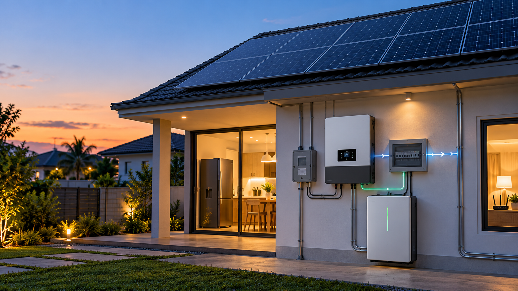
What happens when the grid comes back to a home battery system? The inverter does not simply throw the whole house back onto utility power. It first checks the returning grid, ends the backup island, synchronizes its output and then transfers the supported circuits into normal grid-connected operation.
1. What actually changes when the grid returns?
A hybrid inverter treats grid recovery as a controlled electrical event. The public supply has to be back inside its permitted voltage and frequency range before the inverter reconnects. The backup output must also stop operating as an isolated source before the grid and the inverter are joined again.
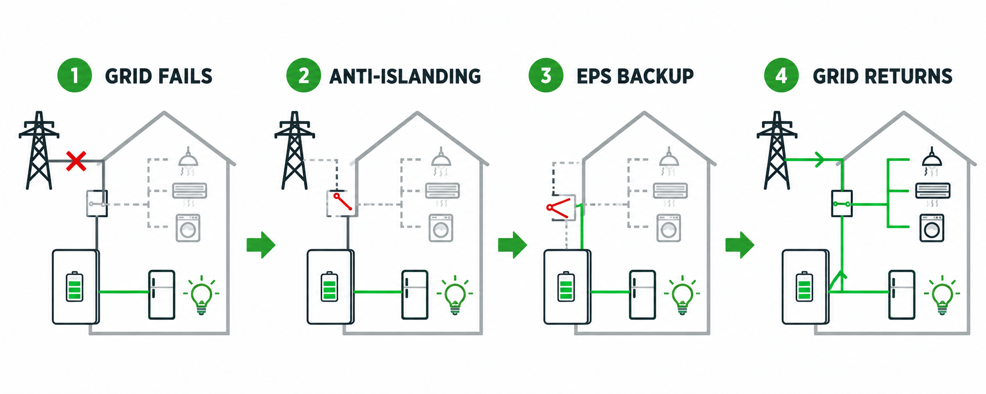
| Stage | Inverter state | What the customer sees |
|---|---|---|
| Grid fails | Grid-connected output stops following the utility supply. | Selected backup circuits transfer to EPS or UPS output. |
| Backup island | The inverter isolates the backup side and forms a local supply from the battery and PV. | Critical loads stay powered; non-backup circuits remain off. |
| Grid returns | The inverter measures voltage, frequency and phase before reconnection. | Backup output may hold briefly or drop during the transfer. |
| Normal operation | The inverter resynchronizes and resumes the configured grid mode. | Grid-side loads return, and battery charging can resume if enabled. |
The exact sequence varies with the inverter architecture, local grid code, firmware and transfer equipment. A product that provides backup output still needs a defined reconnection behavior in its installation documentation.
2. Anti-islanding and backup output do different jobs
Anti-islanding protects the utility network. When the grid is absent or outside the permitted operating window, a normal grid-tied inverter must stop energizing the utility connection. That prevents a disconnected line from remaining energized while utility personnel are working on it.
Backup output solves a different problem. A hybrid inverter with an EPS or UPS port disconnects the backup circuits from the failed grid and creates a local supply for those circuits. The battery and PV can then support the local backup side without feeding the dead utility line.
A standard grid-tied inverter may shut down during an outage. A hybrid inverter may provide a separate EPS output. An external transfer switch or gateway may control the isolation and the return transfer. These are different system architectures.
Grid-connection guidance commonly separates three functions: islanding prevention, automatic reconnection after the grid returns to normal, and synchronization before the connection closes. That is why “the grid is back” and “the backup output has reconnected” are related events, but not the same signal.
3. Which circuits come back first?
The battery does not decide which rooms receive power. The backup output and the critical-load panel decide that. A refrigerator, router, security system, LED lighting and a small fan are typical loads for a selected backup panel. Water heaters, induction cookers, large air conditioners and EV chargers usually stay on the normal grid side unless the system was specifically designed for them.
| Load group | Typical connection | What to check when the grid returns |
|---|---|---|
| Refrigerator, freezer, router and security | Critical-load panel | Compressor restart, short transfer interruption and available inverter power. |
| Lighting, fans and selected sockets | Critical-load panel | Continuous load and total backup energy. |
| Water pump or small air conditioner | Conditional backup load | Running power, starting current, battery current and inverter surge capability. |
| Water heater, induction cooker and EV charger | Normal grid load | Whether the system was designed with enough output and battery power for the load. |
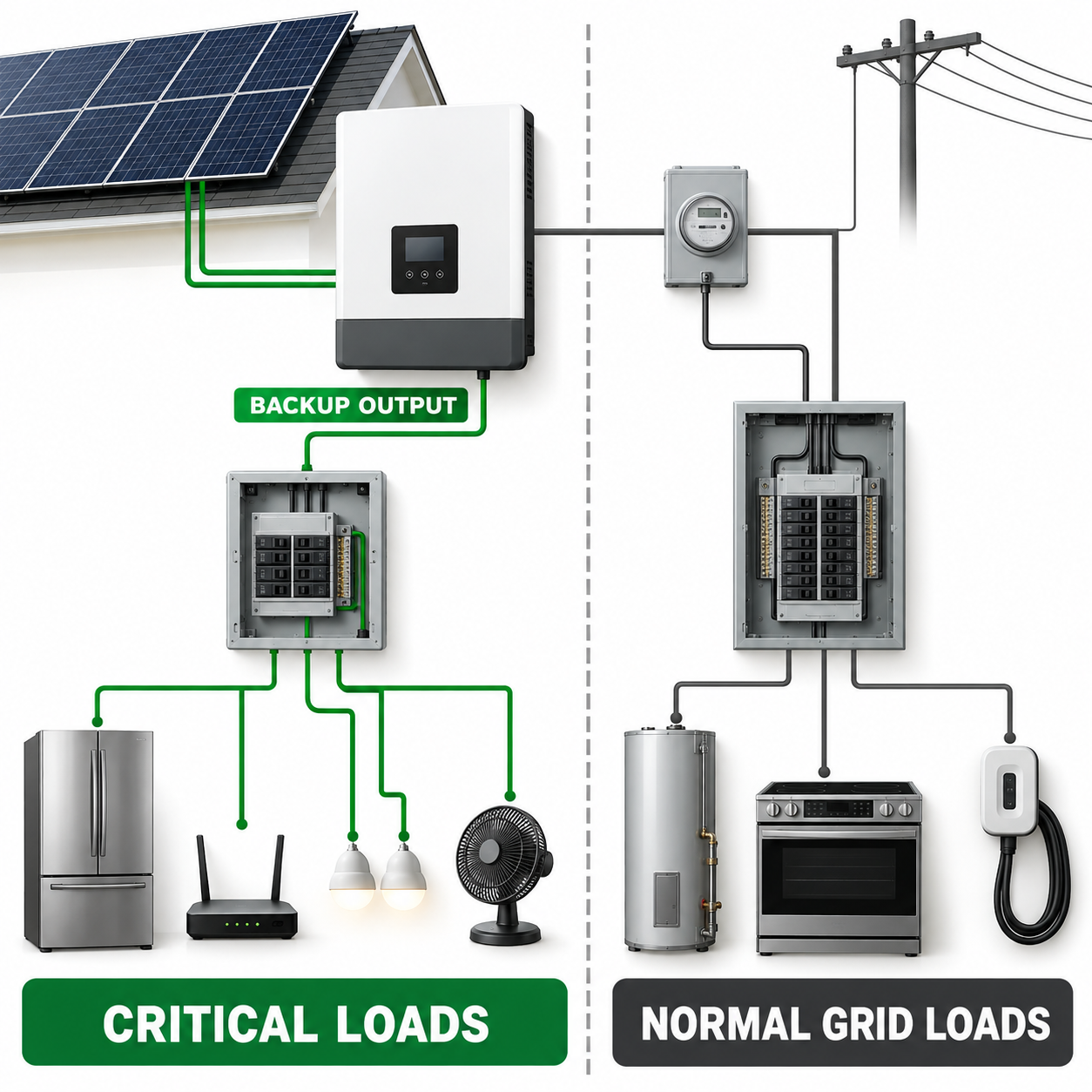
When the grid returns, the inverter may restore the normal grid side before the customer notices the backup circuits change. That is normal system sequencing. The installer should verify the panel arrangement and the expected transfer behavior during commissioning so the customer knows which circuits will return and when.
4. Why can AC output dip during reconnection?
A short power dip during grid reconnection usually comes from the transfer sequence, not from the battery suddenly losing all its energy. The inverter is moving from a locally formed backup waveform to a synchronized grid waveform. The control system checks the returning supply and closes the connection only when the measured conditions are acceptable.
| Parameter or event | How it affects the return | What the installer records |
|---|---|---|
| Grid voltage | An overvoltage or undervoltage condition can delay reconnection. | Measured voltage and the inverter event code. |
| Grid frequency | The inverter waits for a stable frequency window before synchronization. | Frequency at the moment of the transfer. |
| Phase synchronization | The backup waveform must match the returning grid before the connection closes. | Synchronization or reconnect status in the inverter log. |
| EPS or ATS transfer | The backup panel can see a brief interruption while the switch changes source. | Observed transfer behavior and the selected transfer mode. |
| Battery SOC and operating mode | Low SOC, reserve settings or a protection state can limit backup output before the grid returns. | SOC, charge/discharge power and active alarms. |
Keep two timings separate in the project record:
- Grid-to-backup transfer time: how quickly the critical loads receive EPS or UPS power after the grid fails.
- Backup-to-grid reconnection time: how long the inverter waits and synchronizes after the grid returns.
A datasheet may publish the first value and leave the second to the model manual, grid-code setting or commissioning procedure. Do not use an EPS switching figure as the grid-reconnection time.
5. Read the Firefly Hybrid parameters
CVC’s Firefly Hybrid range gives a useful example of how to read these specifications. The range includes Hybrid-3K and Hybrid-4.6K models for residential solar storage and backup applications.
| Firefly Hybrid parameter | Listed figure | How to read it for grid return |
|---|---|---|
| Rated AC output | 3.0 kW / 4.6–5.0 kW, model dependent | Sets the continuous output class for the supported loads. |
| EPS maximum apparent power | Up to 3.6 kVA / 5.0 kVA, according to model and PV condition | Shows the backup-side ceiling. It is not a promise that every household circuit can run together. |
| EPS switching duration | ≤10 ms | Describes the grid-to-EPS transfer specification, not the time needed for grid resynchronization. |
| Grid input | 230 V, 180–270 V; 50/60 Hz configurations | Connect the country version and grid settings to the project’s actual supply. |
| Battery range and current | 40–60 V, rated 48 V; maximum charge/discharge current 66 A | Check the battery voltage window, continuous current and BMS permission together. |
| Communications | CAN / RS485, plus Wi-Fi and GPRS options | Use the correct battery profile and communication setup during commissioning. |
For a 5 kW-class home, the practical reading is straightforward: the inverter can move selected circuits through an EPS output, but the critical-load panel still needs to be sized around the inverter output, motor starting demand and battery current. The product page lists a maximum PV input of 6.6 kW or 8 kW by model, a maximum PV voltage of 550 V and an MPPT range of 120–500 V. Those figures support recharge planning after an outage; they do not enlarge the EPS output ceiling.
The Firefly Hybrid product page lists EPS switching of no more than 10 ms. The model manual and the local grid setting should be used for the exact reconnection wait, auto-restart behavior and generator handover. That is the information the distributor or installer needs when explaining what the customer will see after the grid returns.
See the Firefly Hybrid home solar storage inverter page for the current model range and technical data. For battery voltage, current and CAN/RS485 matching, use the CVC battery compatibility guide as a companion reference.
6. Test the grid-return event before handover
A commissioning test should show the customer what changes when the grid comes back. Record the system state before the test, create the outage condition through the approved installation procedure, and then record the return-to-grid sequence. The installer or qualified service team should carry out the electrical switching and protection checks.
| Test point | Record | Pass condition |
|---|---|---|
| Before the outage | SOC, PV power, grid voltage, frequency, load power and operating mode | The starting condition is clear and repeatable. |
| During backup | EPS output, supported circuits, load power and inverter alarms | Critical loads remain within the configured output and current limits. |
| When the grid returns | Voltage, frequency, event timestamp, reconnect status and any output dip | The inverter waits for stable grid conditions and completes the configured transfer. |
| After reconnection | Grid-side loads, battery charge power, SOC reserve and generator status | Normal operation resumes and the battery follows the configured charging mode. |
Give the customer a simple record: which circuits are on the backup panel, how long the transfer usually takes, what the inverter display shows and which alarm requires service support. A clear handover prevents the common mistake of treating every silent socket or delayed charge as a battery failure.
7. Four questions distributors hear from customers
When the grid returns, does the battery stop immediately?
No. The inverter checks the returning grid and then transfers the operating mode. The battery may continue supporting the critical-load panel until synchronization and the configured return sequence are complete.
Does anti-islanding mean backup power is available?
No. Anti-islanding stops the inverter from energizing a failed utility connection. Backup power requires a hybrid inverter or a separate backup architecture with isolation, a battery or other source, and a defined backup output.
Why do the critical loads return while other sockets remain off?
The circuits are connected to different sides of the system. Critical loads are on the EPS or backup panel; other sockets remain on the normal grid side until the grid-connected supply is restored.
Are EPS transfer time and grid-reconnection time the same?
No. EPS transfer time describes the move from grid to backup output. Grid-reconnection time describes the voltage and frequency checks, synchronization and return transfer after the utility supply comes back.
Sources and model reference
Technical explanations in this article are based on the following public references:
- CVC Energy Firefly Hybrid home solar storage inverter, including model range, EPS switching, grid input, PV range, battery range and communication options.
- Hong Kong EMSD Technical Guidelines on Grid Connection of Renewable Energy Power Systems, covering anti-islanding, automatic reconnection and synchronization concepts.
- U.S. Department of Energy: Solar Integration, Inverters and Grid Services Basics, for the relationship between inverter behavior and grid voltage or frequency events.
For a model-level selection, send the inverter model, battery voltage, critical-load list, expected backup output and target market to the CVC Energy team. CVC can help connect the project with a suitable product route and the relevant supplier documents.

Peter Yin
Need a Home Battery Backup Output Check?
Send the inverter model, battery voltage, critical-load list and target market. CVC can help match the system route and supplier documents.