
All-in-one energy storage error codes can look alarming, but they are usually a starting point for diagnosis—not a reason to open the cabinet. An all-in-one energy storage system is usually purchased for a very practical reason: fewer separate boxes, less external wiring, simpler commissioning and one monitoring interface for the battery, inverter and energy-management functions.
For a small home, a rental property or a compact backup installation, that simplicity matters. A buyer may not want to match a separate battery, hybrid inverter, BMS interface, communications cable, transfer device and monitoring gateway. An integrated system can make the project easier to explain, easier to install and easier to operate.
That same simplicity can make a warning screen feel more serious than it is. The system may show Battery Communication Abnormal, F58, Error 05 or a battery expansion-module alarm. The display may still be on, but charging may have stopped. The owner then has to answer several questions at once:
- Is this a temporary communication interruption or a failed battery?
- Is the inverter protecting itself because of a real overload?
- Can the system be restarted safely?
- Has one module failed, or has the complete system stopped?
- What information will the installer or after-sales team need before they can help?
Modern systems normally identify a functional area, such as the battery, inverter, communications link, grid/PV input or system controller. The important point is that an error code is a diagnostic starting point, not automatically the final root cause. A battery communication fault can involve a cable, port, protocol, address, firmware version or BMS protection state. It does not prove that the battery cells are damaged.
This guide explains how to read all-in-one energy storage error codes, what a customer can safely record or check from outside the equipment, and when the case should move directly to a qualified installer or authorized service team.
Why customers choose an all-in-one energy storage system in the first place
The usual attraction is not only the battery capacity. It is the reduction in system decisions.
An integrated unit can combine a battery pack, hybrid inverter, battery-management interface, charger and monitoring functions in one product family. Depending on the model, it may also provide PV input, grid input, generator input, backup output and a local display. A modular stacked design can be easier to expand than a completely custom installation, while a single product family can reduce compatibility questions during commissioning.
This is particularly useful in real purchasing situations:
- A homeowner wants backup for refrigeration, lighting, internet equipment and selected air-conditioning loads without building a custom system from several brands.
- A small installer wants a repeatable package with a known battery-inverter communication path.
- A rental-property owner wants a compact system that is easier to explain to the next occupant.
- A buyer planning an outdoor system wants the battery, inverter and monitoring path specified together rather than assembled from unrelated parts.
However, “integrated” does not mean “immune to faults” and it does not mean “every problem can be fixed by the owner.” It means the system can often tell you which functional area needs attention. That is valuable because the installer can start with the right manual, log file, cable path or replacement part instead of treating the whole system as a black box.
The customer’s job is not to identify the failed transistor or repair the BMS. The customer’s job is to capture the alert accurately, describe the operating conditions and stop unsafe trial-and-error. That gives the service team a much better starting point.
How to read all-in-one energy storage error codes in four layers
When a message appears, read more than the number.
1. Record the complete code and wording
Write down the exact letters, numbers and English description. F58, Battery Communication Fault and Battery Offline may refer to the same general area but are not interchangeable evidence.
Take a screenshot of the app or a photo of the local display. Record the date and time. If the message disappears after a restart, keep the original screenshot rather than reporting only “it went away.”
2. Identify the fault domain
Most messages can be grouped into one of these domains:
| Fault domain | What it may include | What the code does not prove |
|---|---|---|
| Battery/BMS | Battery status, SOC, module voltage, BMS protection | It does not automatically prove cell damage |
| Inverter/power stage | AC overcurrent, DC overcurrent, internal circuit or MOSFET protection | It does not automatically prove the inverter must be replaced |
| Communications | CAN/RS485 link, address, protocol, firmware or port state | It does not automatically prove the cable is the only cause |
| Grid/PV | Grid voltage, frequency, PV insulation, arc or input state | It does not automatically prove the utility grid is at fault |
| System control | Parallel operation, DRM, overload timeout or controller state | It does not automatically identify the failed physical part |
3. Identify the current operating state
Ask what the system is doing now:
- Is it still supplying the load?
- Has it stopped charging but continued discharging?
- Has it stopped both charging and discharging?
- Is output power reduced?
- Is the system in standby, grid bypass or complete shutdown?
- Is there any abnormal heat, smell, smoke, noise or visible damage?
The same broad fault domain can have very different urgency depending on the current state and the safety symptoms.
4. Identify who is allowed to handle the next step
The model manual may allow a normal restart, but that is not the same as authorizing the customer to change BMS settings, remove a cable or open the enclosure. Read the recovery instruction together with the safety section and the exact model number.
A practical safety triage for error messages
The following is an editorial service-routing framework for this article. It is not a universal L1-L4 standard used by every manufacturer.
| Article triage | Typical situation | Customer action | Service boundary |
|---|---|---|---|
| Observation | The system is still operating and shows a non-critical warning or a temporary status message | Capture the code, time, SOC, PV, grid and load information; observe the outside of the unit | Do not change parameters just to clear the message |
| Function limited | Charging, discharging or output is limited, but there is no smoke, smell or abnormal heat | Reduce non-essential load and follow one normal restart only if the model manual explicitly allows it | Contact the installer if the message returns |
| Professional service | Persistent BMS, internal circuit, MOSFET, insulation, arc, temperature-sensor, bus-voltage or overcurrent fault | Stop repeated restarts and preserve screenshots and logs | Qualified service must diagnose the equipment |
| Safety emergency | Smoke, burning smell, rapid temperature rise, visible damage, short-circuit signs or suspected thermal event | Keep away from the equipment and follow the site emergency procedure | Do not approach the cabinet to continue troubleshooting |
An “L2” or “L3” label in a spreadsheet, ticket system or internal service form should not be treated as a manufacturer-wide definition. The model manual and the actual physical symptoms take priority.
What a customer can safely do before calling service
For most non-emergency alerts, these five steps are useful and low risk:
- Capture the alert. Photograph the local screen, indicator lights and app page. Include the full code, not just the first number visible in a notification.
- Record the identity. Note the complete model, serial number, installation date, firmware version if visible, and country or grid region.
- Record operating conditions. Write down SOC, PV power, grid status, output power and the loads running at that moment. Note whether an air conditioner, pump, refrigerator or other motor load had just started.
- Observe the outside only. Check whether the room or outdoor enclosure is unusually hot, whether vents are obstructed, and whether an external switch or indicator appears different. Do not remove covers or touch DC terminals.
- Follow one documented normal restart, if allowed. Use the exact model manual. If the code returns, do not keep cycling power while hoping the fault disappears. Send the evidence to the installer or after-sales team.
Do not call a cabinet “healthy” merely because it has DC voltage or the display is on. A battery can have voltage while its BMS is offline, while the inverter has blocked charging, or while a protection state is preventing operation.
When not to troubleshoot the system yourself
Move directly to professional service when the message involves:
- internal circuit, MOSFET, power-stage or temperature-sensor faults;
- persistent battery overvoltage, undervoltage or abnormal SOC;
- a BMS communication fault that returns after the permitted basic check;
- PV insulation resistance, arc, leakage or short-circuit protection;
- repeated inverter overcurrent, DC-bus high/low voltage or heatsink over-temperature;
- changes to BMS stop logic, battery protocol, DIP switches, addresses, firmware or protection thresholds;
- opening the cabinet, replacing fuses, contactors, communication boards, BMS units or power modules.
Some manuals expose advanced settings that may appear to clear a warning. That does not make them customer controls. For example, the Deye AI-W5.1 manual references a BMS_Err-Stop setting in the context of BMS communication faults. A customer should not disable a protection function to keep a system running. An installer or authorized service professional must decide whether any configuration change is safe for the specific battery, firmware and operating mode.
Model walkthrough 1: Deye AI-W5.1
The Deye AI-W5.1 is a useful example because its manual separates several fault domains instead of presenting every event as a generic battery problem. The AI-W5.1 family combines a low-voltage battery system with a 5 kW to 12 kW three-phase hybrid inverter range and uses a local display alongside monitoring and communication ports.
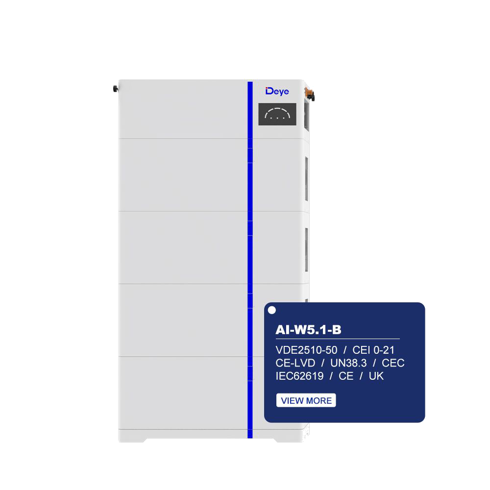
F58: BMS communication fault
F58 points to a communication problem between the inverter and the battery-management system. The useful interpretation is not “the battery is dead.” The useful interpretation is: the inverter is no longer receiving the battery information it expects.
Possible service causes include a communication cable or port issue, an incorrect protocol or address, firmware mismatch, a BMS protection state, or a battery-side controller that has stopped responding. The customer cannot distinguish those causes from the code alone.
The customer should record:
- the exact F58 message and time;
- battery SOC and whether the battery icon is online or offline;
- whether charging, discharging or both have stopped;
- any recent installation, battery expansion, firmware update or configuration change;
- whether the code returns after the model-approved normal restart.
The installer or authorized service team should then verify the communication path, protocol, firmware compatibility and battery event log. A visible battery voltage is not proof that the BMS communication path is healthy.
F15/F18: AC overcurrent
These codes should be read alongside the load that was running. A customer can first switch off non-essential loads from the normal user side, especially if an air conditioner, pump, compressor or other motor load started just before the alarm. If the error repeats during the same startup event, the service team should check starting current, load distribution, backup-output wiring and protection settings.
The practical lesson is important for a small home system: a 5 kW inverter may be able to operate a 12,000 BTU mini-split under steady conditions but still react to the unit’s starting demand, the battery’s available power and the PV contribution at that moment. A single customer report of a startup trip is not proof that every 5 kW system will fail with the same air conditioner. It is a reason to match continuous power, surge capability, battery discharge power, wiring and operating mode together.
F20: DC overcurrent
F20 is an inverter-side DC overcurrent protection event. It should not be simplified to “the battery is overcurrent.” The event may relate to a battery or PV operating condition, a large off-grid load, wiring, a protection device or an internal power-stage condition.
The customer can record whether the system was on-grid or off-grid, what load had just started, the SOC and the PV input. The customer should not unplug DC connectors or attempt to measure the battery side. A persistent F20 belongs with qualified service.
F64: heatsink high temperature
For a temperature-related code, the customer can record the outdoor or room temperature and check whether the external ventilation path is blocked. If the manual allows a normal shutdown and restart, that can be done once. If F64 returns, or if the fan, enclosure or surrounding area shows an abnormal condition, the installer should inspect airflow, installation clearance, thermal sensors and operating limits.
Model walkthrough 2: Alpha ESS SMILE
Alpha ESS SMILE is a useful example of why the exact product family and manual version matter. Current SMILE residential systems are positioned around integrated battery-inverter operation, with LFP battery technology and outdoor-capable variants, but the alarm meaning still depends on the specific model, firmware and manual.
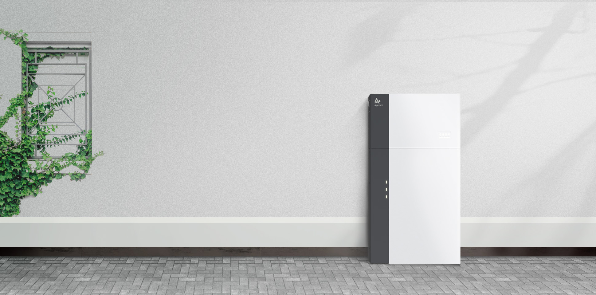
Error 01: confirm the exact manual before interpreting it
In the SMILE-S5 manual family, Error 01 is associated with a temperature-sensor failure. Other SMILE documentation can label Error 01 more generally as a hardware error. That difference is not a contradiction to hide; it is a reason to identify the complete model and document version before telling a customer what the number means.
The safe customer action is to capture the code, note the operating temperature and follow only the permitted basic restart procedure. If the code remains, the service team should inspect the sensor circuit and event history. The customer should not open the battery cabinet to look for a loose sensor.
Error 05: hardware or MOSFET-related fault
Error 05 is a professional-service case in the referenced SMILE documentation. It is not a prompt to remove the cover, test the MOSFET or replace a board. The value of the code is that the service team can prepare the correct diagnostic path and determine whether the system needs a component, a module or a broader inspection.
Error 06: circuit breaker open
An open breaker can look simpler than a hardware fault, but the recovery sequence still matters. The manual requires the battery system to be shut down before the relevant breaker operation. A customer should not repeatedly reclose a breaker while the system is active, nor assume that a tripped breaker is the root cause.
The service team should establish whether the breaker opened because of an overload, short-circuit condition, protection event or an earlier installation issue. “The breaker is open” describes the visible state; it does not explain why it opened.
Model walkthrough 3: Huawei LUNA2000
Huawei LUNA2000 is included here as a reference for reading detailed battery-module alarms. It is a modular battery and inverter ecosystem, not a generic architecture for every all-in-one product. That distinction matters: use its alert-reading method as a model-specific example, not as a universal code list.
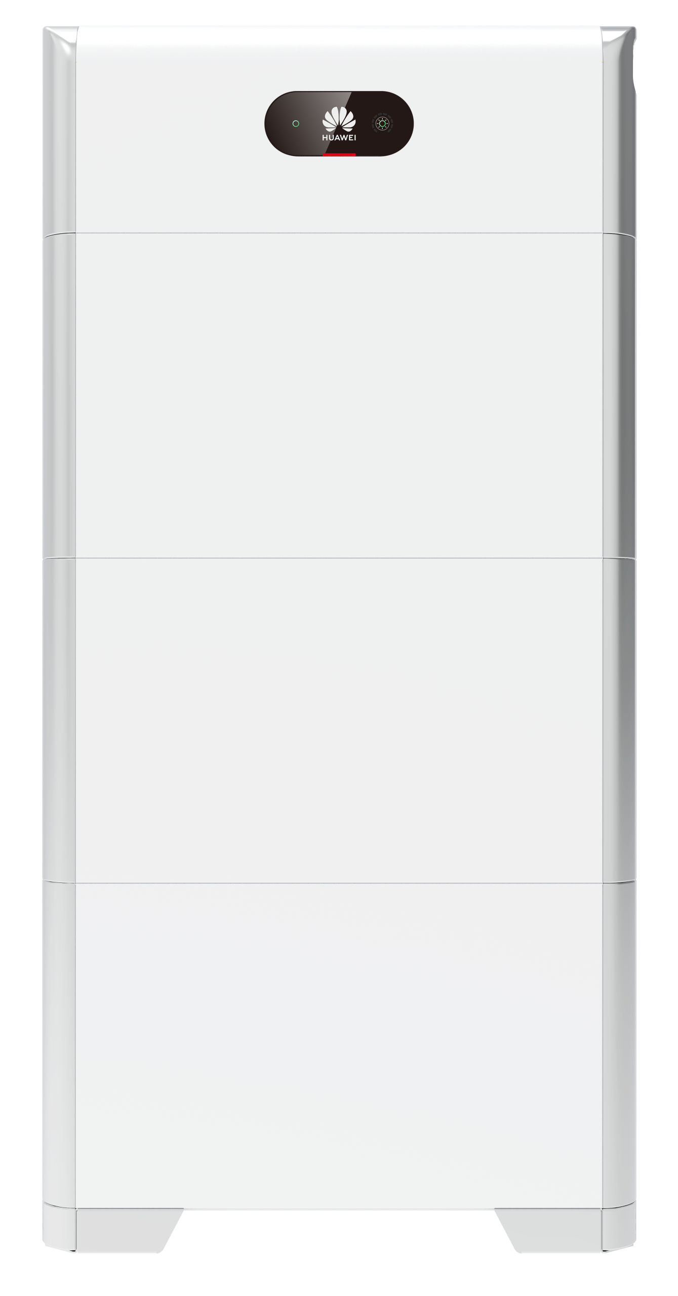
3006: abnormal battery expansion module
The Huawei support path treats 3006 as an abnormal battery expansion-module condition. The useful information for service is the cause ID, the affected module position, the time of the event and whether the alarm returns after the documented shutdown and restart sequence.
The customer should not open the module, move it to another position or repeatedly disconnect and reconnect the battery stack. The installer should follow the manufacturer’s shutdown order, inspect the module and cable path, and escalate if the alarm remains.
3007 or 3007-1: module or cable communication direction
In the referenced LUNA2000 manual family, 3007-series alarms point toward a battery expansion-module cable or module communication condition. The number is useful because it narrows the service path, but it still does not tell the owner which physical part must be replaced.
When reporting the alarm, provide the module location shown in the app, the cause ID, the battery SOC, the recent installation or expansion history and a screenshot of the full alarm page. That information is more useful than a message such as “the battery is not working.”
Communication faults are not always cable faults
Across residential storage systems, a battery-offline or communication-fault message can have several layers:
- The physical cable or connector may be damaged, incorrectly wired or connected to the wrong port.
- The communication protocol may not match the selected battery type.
- The address, DIP setting or termination may be incorrect in a multi-module system.
- The firmware versions may not support the selected combination.
- The BMS may have entered a protection state and stopped normal communication.
- The inverter may be receiving data but rejecting it because a required parameter is missing or outside the permitted range.
That is why a customer should not unplug and reconnect communication cables based only on a message in the app. Give the installer the model, code, screenshot, firmware and recent change history. The professional can then check the communication topology and configuration in the correct order.
Grid, PV and system-level alerts need operating context
Grid voltage or frequency alerts
A code such as Deye F42 points toward an AC-line low-voltage condition in the referenced AI-W5.1 manual. The customer can record whether the grid had just gone off, whether other heavy loads started, and whether the event happened only during a generator or backup transition. The actual voltage and frequency measurement, protection settings and local grid rules belong to the installer or electrician.
PV insulation or arc alerts
PV insulation and arc-related messages are not normal “check the cable” tasks for an end customer. Stop repeated restart attempts and contact qualified service. The DC side may remain hazardous even when the display is off. The service team must follow the site isolation procedure and use appropriate test equipment.
DRM or external-control stop signals
Some markets use demand-response or external control signals. A code such as Deye F62 can indicate a DRM0 stop condition rather than a failed battery. The customer should not disable the function or change the grid profile just to remove the alert. The installer should confirm whether the signal is expected for the site and market.
Overload timeout
If the system reports an overload timeout, the customer can turn off non-essential loads from the normal user side and record which load was running. If the event occurs every time a compressor, pump or air conditioner starts, the service team should compare starting current, continuous load, inverter surge capability, battery discharge power and backup-circuit design. Capacity is not only a kWh question.
What real customer situations tell us about the right diagnosis
Customer feedback shows why a simple “read the code and replace the battery” article is not enough. These are anonymized signals from recent public customer discussions and planning conversations. They are not failure-rate statistics.
“If one module fails, does the whole all-in-one system stop?”
One recent all-in-one discussion focused on the perceived single-point-of-failure risk: one module could stop the complete unit, the owner might not know which part failed, and proprietary parts could make repair slow. The practical answer is not to promise that every system remains online after a module fault. The better answer is to ask what the system reports, whether it identifies a battery, inverter or communication domain, and what the manufacturer’s replacement and service path looks like.
This is also why error-code documentation belongs in the purchasing decision. A clear alert does not eliminate downtime, but it can reduce the time spent guessing.
“I need a 30 kW battery and a 12 kW inverter, with generator input and outdoor installation.”
Another customer was planning a larger system with generator input, outdoor installation and high-temperature concerns. In that situation, the error-code conversation begins before installation. The buyer should ask for operating-temperature limits, thermal derating behavior, generator compatibility, overload handling, backup-load limits and the exact service workflow for high-temperature or grid-transition alerts.
“My 5 kW all-in-one trips when the mini-split starts.”
This field report involved a 5 kW all-in-one system and a 12,000 BTU mini-split. The useful lesson is not that the combination is universally incompatible. It is that startup current, PV power available at that moment, battery discharge limit, inverter surge capability and backup wiring can interact. A system that runs the air conditioner after startup may still trip at startup.
When an AC-overcurrent code appears, record the load and timing. Do not reduce the problem to the nameplate capacity alone.
“The SOC said 100%, then the battery was almost empty in the morning.”
Another customer report described an unexpected SOC change followed by a charging-controller problem. That sequence cannot be diagnosed from the SOC number alone. A service team needs the event log, charging source, standby load, battery voltage, BMS state and any subsequent hardware alarm.
The lesson for an all-in-one buyer is simple: save the app history before resetting the system. A screenshot of the final state is less useful than a timeline showing what happened first.
“The low-voltage alarm and breaker trip are now a communication-board dispute.”
Recent battery discussions also show how a low-voltage alarm, a breaker trip and a suspected communication-board problem can become one long replacement dispute. A good service handoff separates the stages: what the system displayed, what protection operated, what was tested, what was replaced and whether the new part changed the alarm.
What to send the service team in one message
Copy and complete this checklist before opening a support case:
Product and model:
Serial number:
Installation country and date:
Firmware/app version, if visible:
Exact error code and wording:
First occurrence: date and time:
Does the system still operate? Charging / discharging / backup output:
SOC at the time:
PV power and grid status:
Output power and major loads running:
Did an air conditioner, pump, compressor or refrigerator just start?
External temperature or unusual ventilation condition:
Indicator-light status:
Smoke, smell, abnormal heat or visible damage: yes / no
What happened after the model-approved normal restart:
Recent expansion, firmware update, wiring or parameter change:
Photos or screenshots attached: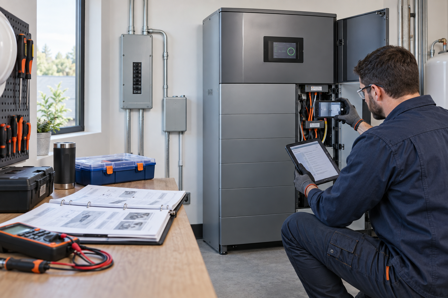
This format helps the installer distinguish a one-time event from a recurring fault. It also reduces the risk that a customer is asked to repeat unsafe checks simply because the first report was too vague.
What buyers should ask for before purchasing an all-in-one system
Error-code support is part of product fit. Before placing an order, ask the supplier or manufacturer for:
- the troubleshooting and alarm-code manual for the exact model and market version;
- the current firmware and compatibility list for the battery, inverter and monitoring platform;
- the normal recovery procedure for communication, over-temperature, overload and grid faults;
- a clear list of customer-safe actions versus installer-only actions;
- the replacement path for BMS, communication boards, fans, contactors and power modules;
- expected service response, spare-parts availability and warranty responsibility in the destination country;
- the data that the app or gateway can export when an alarm occurs.
This is especially important for customers concerned about repairability or single-point-of-failure risk. A compact cabinet is attractive, but the purchasing decision should include the diagnostic interface and the after-sales path, not only the battery capacity and inverter power.
How CVC can help with the sourcing side
CVC can help buyers compare the exact model, application requirements, technical documents, factory route and after-sales information before a product is selected. That may include matching capacity and output power, checking outdoor and temperature requirements, confirming communication interfaces, and requesting the correct troubleshooting documents for the target SKU.
For a product such as a residential all-in-one ESS, a public product page is not a substitute for the model-specific alarm table. Before an order is finalized, the buyer should receive the applicable manual, firmware range, service contact and responsibility matrix for the actual market version.
CVC’s role is to help coordinate product and supply information with the appropriate manufacturing and service partners. It does not replace an authorized installer or service technician for internal electrical diagnosis and repair.
Frequently asked questions
Can I restart an all-in-one system after an error code appears?
Only if the exact model manual permits a normal restart and there are no safety symptoms. Follow the documented sequence once. If the code returns, stop repeating the cycle and send the code, screenshot and operating conditions to the installer.
Does a battery communication fault mean the battery is damaged?
No. It may involve the cable, port, protocol, address, firmware or a BMS protection state. The code identifies a communication path or domain; professional diagnosis is needed to identify the root cause.
If a breaker is open, can I simply close it again?
Not automatically. First establish why it opened and follow the exact shutdown and reclose procedure for the model. Repeatedly reclosing a protection device can make a fault worse.
Is an overcurrent code proof that the inverter is too small?
No. The service team needs to compare continuous load, starting current, inverter surge capability, battery discharge power, PV contribution, wiring and operating mode. A motor load can create a short startup event that is not visible in the average power number.
Why can the same-looking error number mean different things on different products?
Error codes are defined by the manufacturer’s firmware and product architecture. Even within one brand, a code may change meaning between product families or manual versions. Always record the complete model and use the matching manual.
What should I photograph before asking for service?
Photograph the local display, app alarm page, indicator lights, model and serial label, external switch position and the surrounding installation condition. Do not remove covers or expose internal wiring to obtain a better picture.
Final takeaway
An all-in-one energy storage system is chosen because it reduces system complexity. When an alert appears, the right response is to keep that complexity from becoming guesswork.
Read the complete code. Identify the fault domain. Record the operating conditions. Separate a safe external observation from a service-only action. Then give the installer the model, screenshot, timeline and log information needed to diagnose the system efficiently.
The clearest error message is useful only when it leads to the correct next step. In most cases, that next step is not opening the cabinet. It is a better service handoff.

Peter Yin
Send a Project Inquiry
Tell us your country, target model, application, expected loads and after-sales documentation needs.