
For a Southeast Asian solar project, battery and inverter matching is a system check. Voltage labels and a CAN or RS485 port are not enough to approve a quotation.
This battery and inverter matching Southeast Asia checklist is written for solar installers and distributors who need a documented pairing before they quote a project.
A battery can look compatible on paper and still fail during commissioning because the BMS profile is unsupported, the firmware is wrong, charge current is limited, or the installation environment pushes the equipment outside its validated operating range. This checklist gives solar installers and distributors a practical order for checking the pairing before they promise a delivery date or a finished system.
Start with the system, not the product names
Begin with the country, grid, installation location, and operating mode. Then define the battery voltage window, usable energy, inverter power, PV input, backup loads, generator requirements, and expected expansion. Only after those points are clear should you compare model numbers.
For each candidate pair, keep the battery datasheet, inverter manual, BMS communication document, firmware information, wiring diagram, and target-country requirements together. A model name copied from an old quotation is not technical evidence.
The pre-quotation compatibility checklist
- Electrical window: Confirm nominal voltage, operating voltage, maximum charge voltage, minimum discharge voltage, maximum continuous current, peak current, and the number of battery modules allowed in parallel.
- Power and energy: Match usable battery energy to the load profile and inverter output. Adding kWh does not automatically add kW; the BMS and inverter may still limit current.
- Communication: Confirm CAN or RS485 wiring, pinout, baud rate, termination, protocol profile, register map, message frequency, and fault-handling behavior.
- Operating modes: Check on-grid, backup, off-grid, generator, and restart behavior. Confirm whether the inverter needs a specific battery brand or profile selected in its firmware.
- Protection: Review pre-charge, contactor control, insulation monitoring, over-temperature protection, short-circuit protection, and the response to a lost communication link.
- Installation: Check IP rating, temperature range, humidity, condensation risk, salt exposure, rain, insects, clearances, ventilation, and the service access required after installation.
- Evidence: Ask for model-specific manuals, test reports, firmware notes, compatibility records, and a sample validation plan before the combination is presented as approved.
Communication protocols are the core matching check
Communication is where a nominally compatible battery and inverter either become one system or remain two separate products. Both devices may have a CAN port, but that does not mean they speak the same message language. The installer needs the profile, not just the connector.
- Protocol profile: Identify the exact profile, such as Pylon, Victron, SMA, or a manufacturer-specific map.
- Physical layer: Confirm CAN or RS485, pinout, cable type, shielding, termination, isolation, and maximum cable length.
- Speed and addressing: Confirm baud rate, node address, master and slave roles, and whether parallel batteries need a communication hub.
- Data exchanged: The battery should report SOC, SOH, voltage, current, cell or pack temperature, alarms, contactor state, and charge/discharge limits. The inverter must use those limits rather than applying a generic value.
- Fault behavior: Confirm what happens after a communication timeout, CRC error, invalid SOC, sensor fault, or a battery contactor opening.
- Firmware: Record the exact battery and inverter firmware versions used during validation. A later firmware update can change the supported profile or the current limits.

CVC battery-to-inverter compatibility reference
The table below is the current compatibility reference shown on the CVC Products page. It is a starting point for technical review, not a blanket approval for every model in a brand family.
| Inverter brand | Protocol / profile | Communication |
|---|---|---|
| Deye | Pylon | CAN / RS485 |
| Deye | Low-voltage hybrid inverter | CAN 500 kbps |
| Growatt | Growatt | RS485 / CAN |
| Growatt | Pylon | RS485 / CAN |
| GoodWe | GoodWe | CAN |
| GoodWe | Pylon | CAN |
| Ginlong (Solis) | Ginlong | CAN |
| Victron | CAB-BUS BMS Protocol | CAN |
| Victron | Victron | CAN |
| SMA | FSS-ConnectingBat-TI-en-10 | CAN |
| SMA | SMA | CAN |
| Luxpowertek | Luxpowertek | RS485 / CAN |
| MEGAREVO | MEGAREVO | RS485 |
| Voltronic | Pylon | RS485 |
| Voltronic | Voltronic | RS485 |
| Sofar | Pylon | RS485 |
| Sofar | Sofar | CAN |
| SRNE | Pylon | RS485 |
| SRNE | PACE | RS485 |
| SRNE | WOW | RS485 |
| Afore | Afore | CAN / RS485 |
| Aiswei | Aiswei | CAN |
| GT | RS485 Inverter | RS485 |
Before a quotation is fixed, confirm the exact inverter model, battery voltage, BMS profile, communication version, firmware, parallel configuration, and destination-country requirements. If any of those variables changes, the pairing should be reviewed again.

Site conditions in Southeast Asian projects
Southeast Asian projects can combine high ambient temperature, strong solar radiation, high humidity, condensation, salt air, heavy rain, insects, standing water, lightning, and different grid or generator conditions. Treat these as product-selection and commissioning inputs, not details to leave until the end.
High-temperature environments
Applicable scene: Ambient temperatures of about 42-50°C, outdoor installation, and direct solar radiation that raises the temperature inside the enclosure.
Overall requirements
- Use 45°C operation at rated power as a tropical-market selection target.
- Above 45°C, apply a defined power-temperature derating curve.
- At 50°C, controlled derated operation may be acceptable only when the derating percentage, minimum output power, and over-temperature shutdown point are stated.
- Avoid accelerated cell ageing, overheated power devices, and repeated shutdowns caused by high temperature.
Battery PACK
BMS temperature control
The BMS should act on the highest cell temperature, not only ambient temperature. Check for this control sequence:
- High-temperature warning.
- Charge-current limitation.
- Charge and discharge power limitation.
- Over-temperature charge or discharge stop.
- Delayed restart after the temperature returns to a safe range.
High-temperature operation should limit high-current charging to reduce side reactions and capacity loss.
Cell selection
Use LFP cells intended for stationary storage with a wide operating temperature range. Check:
- Continuous charge temperature range.
- Continuous discharge temperature range.
- Permitted charge and discharge rates at high temperature.
- Test temperature and conditions used for cycle-life data.
Storage temperature is not a substitute for an operating-temperature specification.
Thermal structure
Wall-mounted and stacked battery packs should:
- Keep cells and the enclosure out of direct sunlight.
- Maintain the specified installation clearances.
- Use enclosure conduction, heat-dissipation features, or natural convection to reduce internal temperature rise.
- Avoid sealed, unvalidated closed-box structures.
BMS and electrical component derating
Rate the following parts for the highest actual internal temperature, not the outdoor ambient reading alone:
- BMS controller, MOSFETs or relays, and sampling circuits.
- Fuses, connectors, busbars, and other current-carrying parts.
- Capacitors, including their ripple-current and service-life calculation.
- Thermal interfaces and materials used around power components.
A 105°C capacitor rating is a component limit. It does not mean the equipment can operate in a 105°C ambient environment.
High-temperature life management
Request evidence that the BMS can:
- Record accumulated high-temperature operating time.
- Record the temperature ranges reached during operation.
- Upload the data to the monitoring platform.
High-temperature cycle-life results should state test temperature, charge and discharge rate, SOC window, and test conditions. Do not copy a 25°C laboratory cycle-life number into a tropical-market claim or use a fixed degradation percentage without test evidence.
Hybrid energy storage inverter PCS
Power derating curve
A tropical-market inverter should target:
- 100% rated output at 45°C.
- Gradual derating above 45°C.
- Controlled output at 50°C.
- A complete power derating curve with test conditions.
Cooling system
Active air cooling, fan-assisted cooling, or natural cooling may be used according to power level, but the design must be validated at high temperature. Fan-cooled models should provide:
- Adaptive fan speed.
- Fan failure or stall alarms.
- Dust and insect protection.
- Clear inlet and outlet clearance requirements.
- Temperature protection after airflow is blocked.
Power device selection
Do not specify IGBT as a universal requirement. Depending on power level, an inverter may use IGBT, MOSFET, or SiC devices. Check:
- Semiconductor junction-temperature and derating design.
- High-temperature capability of inductors, transformers, relays, and busbars.
- Capacitor ripple current and service life.
- Long-term reliability of thermal materials and interfaces.
Over-temperature protection
The inverter should provide this protection sequence:
- Temperature warning.
- Power derating.
- Over-temperature shutdown.
- Safe restart after recovery.
High humidity and internal condensation
Applicable scene: Relative humidity of about 70-95%, large day-night temperature swings, and possible internal condensation without obvious water ingress. The risks include PCB corrosion, lower insulation performance, oxidized terminals, poor connector contact, and intermittent short circuits.
Battery PACK
Protection rating
- Outdoor wall-mounted products should generally be at least IP65.
- For heavy rain, coastal, or island environments, consider IP66 first.
- Indoor garage products may use IP54 when the installation is suitable, but condensation risk still needs review.
- IP20 indoor products are not suitable for outdoor Southeast Asian installation.
PCB and terminal protection
Document the protection applied to BMS, sampling, and high-voltage control boards:
- Conformal-coating type suited to the circuit.
- Coating thickness and coverage.
- Inspection method and acceptance criteria.
- Corrosion-control treatment for connectors, relays, terminals, and busbars.
Depending on current and exposure, busbars may use tin, nickel, or another validated surface treatment.
Seals and cable entries
- Use seals that resist humidity, UV, and long-term compression set.
- Use cable glands matched to the product IP rating.
- Provide drip loops so water does not travel along a cable into the enclosure.
- After maintenance, confirm the seal again.
Insulation and isolation
After damp-heat testing, confirm that the following still meet the design requirements:
- Insulation resistance.
- Dielectric strength.
- Leakage current.
- Protective earthing.
High-voltage battery systems should include insulation monitoring, low-insulation alarms, and contactor disconnection as required by the architecture.
Condensation control
Coastal and humid projects may need:
- Electrical-compartment temperature and humidity sensing.
- Dew-point calculation.
- Anti-condensation heaters.
- Heater-fault alarms.
The heater should keep PCBs, terminals, and relay surfaces above the dew point. It is not a method for heating the cells.
Structure
Separate the battery compartment from the electrical control compartment where practical. Provide reliable drainage and pressure-equalization paths, and avoid direct hot-cold air impact on circuit boards.
Hybrid energy storage inverter PCS
- Use IP65 or higher for outdoor PCS products; assess IP66 for heavy-rain, island, and wash-down environments.
- Apply suitable conformal coating and corrosion protection to control boards, power boards, and key connections.
- Design the airflow path to balance water, dust, insect, and heat protection. Do not direct humid outside air onto PCBs.
- Check insect screens for pressure drop, blocked-filter temperature rise, and maintenance intervals.
- Consider cabinet temperature/humidity sensing and anti-condensation heating.
- Use reliable waterproof terminals or glands for AC, DC, and communication cable entries.
- Reduce moisture exchange caused by day-night temperature changes through proper cable-entry and enclosure design.
Salt-spray corrosion
Inland and coastal sites need different corrosion designs. C4 and C5-M can guide environment classification and coating selection, but neither class alone proves the corrosion performance of the complete product.
Battery PACK
- Use a corrosion solution assessed for C4 conditions at inland sites.
- Assess coastal, island, and high-salt environments for C5-M or higher.
- Include the enclosure, cut edges, screw holes, earthing points, and fasteners in the corrosion design.
- Prefer 316 stainless or validated corrosion-resistant fasteners for coastal projects.
- Use nickel, tin, or another suitable treatment on busbars and terminals.
- Isolate dissimilar metals to reduce galvanic corrosion.
Hybrid energy storage inverter PCS
- Use coatings or surface treatment suited to marine exposure on aluminium or die-cast aluminium enclosures.
- Protect PCBs, terminals, connectors, and fasteners against corrosion.
- Request salt-spray or cyclic-corrosion evidence.
- If at least 500 hours of salt-spray testing is required, record the standard, method, sample condition, and acceptance criteria.
Heavy rain, insects, and standing water
Battery PACK
- Install above the local design flood or standing-water level.
- Keep the pack off the ground and away from low points.
- Protect cable entries against rainwater backflow.
- Treat ordinary drainage, pressure equalization, and thermal-runaway pressure relief as separate designs.
- Do not drill random holes in the bottom to improve drainage.
- Use insect screens on ordinary vents, but never block safety relief or thermal-runaway exhaust paths.
Hybrid energy storage inverter PCS
- Provide drainage channels or paths.
- Avoid bottom openings exposed to splash.
- Use insect protection on vents.
- Keep the unit away from low points, wall-corner pooling, and concentrated roof discharge.
- Make insect screens and filters accessible for cleaning and replacement.
Lightning and surge protection (SPD)
Battery PACK
- Assess DC-port protection against system architecture, cable length, and lightning risk.
- For long external battery cables, assess whether battery-side surge protection is needed.
- Use isolated transceivers, shielded grounding, and suitable surge protection on CAN and RS485 ports.
- Strengthen common-mode and differential-mode protection where communication cables enter the enclosure.
- Validate surge immunity at external communication ports.
Hybrid energy storage inverter PCS
- Assess SPD protection on the AC and PV DC sides for outdoor PV systems.
- Select Type 1+2 or Type 2 according to the building lightning-protection system, lightning risk, cable length, and local code.
- Match system voltage, maximum discharge current, voltage protection level, and backup protection.
- Keep earthing and equipotential bonding reliable.
- Connect SPD failure indication and remote alarms to the monitoring platform where possible.
Grid characteristics and generator compatibility
Battery PACK
- Support stable CAN or RS485 communication.
- Include charge and discharge current limits, SOC, SOH, temperature, alarms, and contactor status in the protocol.
- Provide timeout handling, CRC checks, and interference resistance.
- Confirm pre-charge, contactor control, and on-grid/off-grid state changes.
- Provide the actual compatible inverter models and protocol versions.
Hybrid PCS frequency and country version
The Philippines uses a 60Hz grid, so confirm 60Hz firmware and the relevant grid parameters. Most other Southeast Asian markets use 50Hz, but “Southeast Asia version” is not a sufficient configuration. Confirm for each country:
- Rated voltage.
- 50Hz or 60Hz frequency.
- Single-phase or three-phase operation.
- Neutral and earthing method.
- Grid-protection parameters.
- Utility or certification requirements.
Grid response
The specification should state:
- AC voltage and frequency ranges.
- Under- and over-voltage protection.
- Under- and over-frequency protection.
- Weak-grid behavior.
- Power factor and reactive-power control.
- Harmonic limits, anti-islanding, reconnection time, and country-level grid parameters.
On-grid and backup transfer
Define the target EPS/UPS transfer time with the test conditions:
- Grid-to-backup or backup-to-grid direction.
- Load type.
- Whether motors or air conditioners are included.
- Whether an external ATS is required.
- Battery SOC and output power at the time of test.
Diesel generator
Confirm which functions are supported:
- Generator input.
- Generator start/stop control.
- Generator and storage coordination.
- Synchronized parallel operation.
If synchronized operation is required, confirm synchronization control, reverse-power protection, earthing, power limits, and certification.
Supplier documents and acceptance files
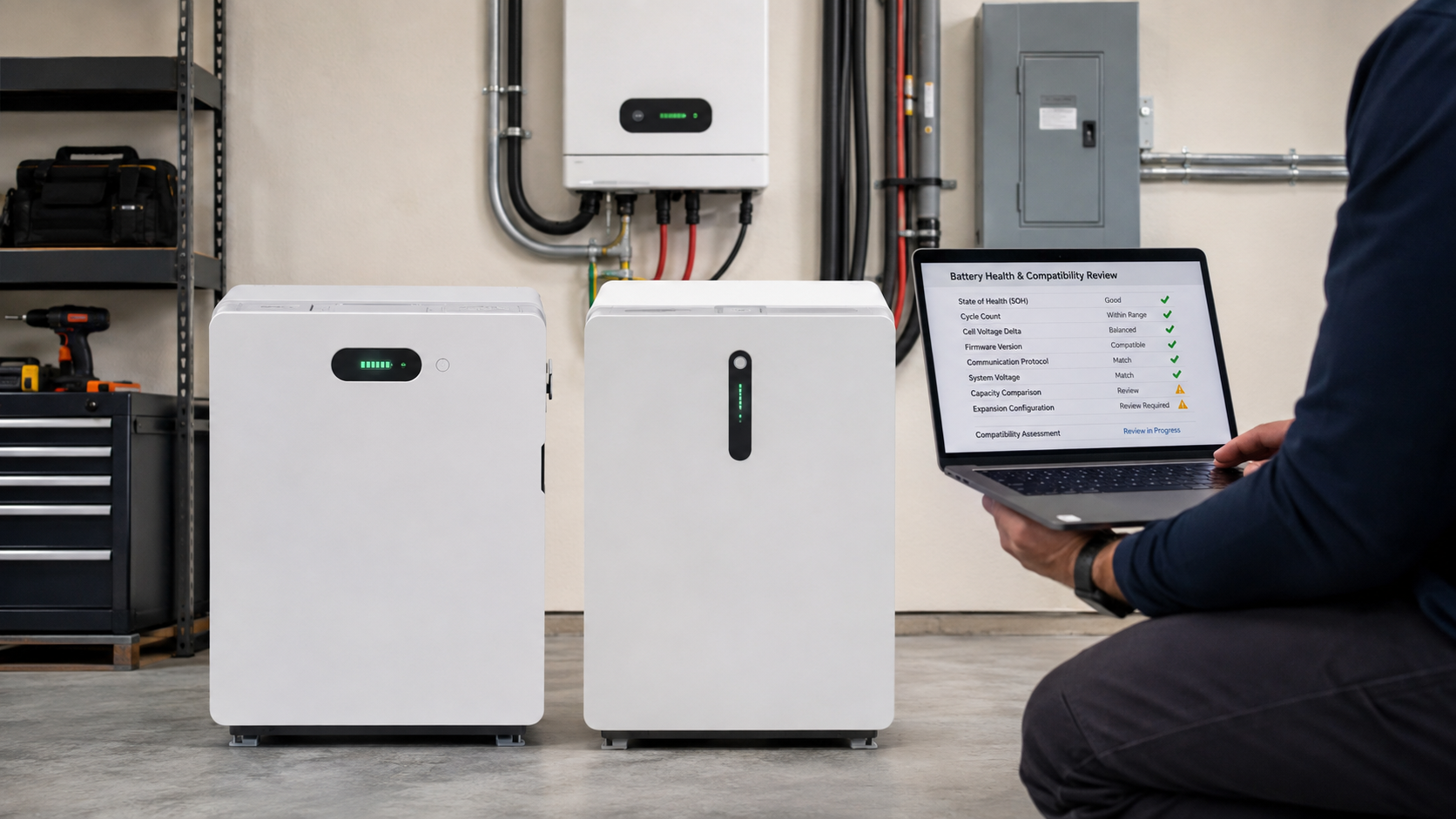
Before quotation or shipment, request evidence that matches the project. Use the list below as a document gate, not as a generic brochure request.
- 45°C and 50°C power-derating curves.
- Cell continuous charge and discharge temperature ranges, plus high-temperature cycle data.
- IP test reports and damp-heat or condensation validation.
- Salt-spray or cyclic-corrosion test reports.
- AC, PV DC, battery, and communication-port surge-protection design.
- Target-country 50Hz/60Hz firmware and grid parameters.
- Battery-to-inverter protocol and compatible-model list.
- Anti-condensation, over-temperature, fan-fault, and SPD-failure alarm descriptions.
Information to send before requesting a quote
Send the country and city, indoor or outdoor installation, single- or three-phase system, grid frequency and voltage, PV size, required backup loads, battery energy and voltage target, inverter power, generator details, expected quantity, and candidate models. Add photos or a simple site sketch when heat, rain, salt exposure, cable distance, or standing water may affect the design.
For a first review, CVC Energy can use that information to select a current battery and inverter pairing, identify missing documents, and separate a confirmed match from a pairing that still needs sample or engineering validation.
FAQ
Is a CAN port enough to prove compatibility?
No. The protocol profile, wiring, baud rate, data map, firmware, current limits, and fault behavior also need to match.
Does a 48V battery work with any 48V inverter?
No. The operating voltage window, BMS profile, maximum current, firmware, parallel limits, and protection logic can still prevent a valid pairing.
Can the Products page table replace model validation?
No. It is a compatibility reference for starting the review. The exact model, firmware, voltage, communication version, and destination-country requirements must be confirmed before quotation.
What is the most common Southeast Asian site risk?
There is no single risk for every project. High heat, condensation, salt air, heavy rain, insects, lightning, and grid differences often overlap, so the site conditions should be reviewed as one system rather than as isolated checklist items.
Confirm the pairing before fixing the commercial offer
A compatible battery and inverter combination is a documented system decision. Check communication first, then verify the electrical limits, firmware, protection behavior, tropical site conditions, and country grid requirements. If the supplier cannot provide model-specific evidence, keep the combination in review instead of presenting it as approved.
Download product documents or contact CVC Energy for a battery and inverter matching review.

Peter Yin
Request a Battery and Inverter Compatibility Review
Send us your country, system mode, load list, PV details, candidate battery and inverter models, and expected quantity. We will help identify the documents and technical checks required before a commercial offer is fixed.